Differential feeding three-frequency planar antenna

A technology of differential feeding and planar antenna, which is applied in the field of mobile communication, can solve the problems of complicated ultra-wideband filter antenna structure design, difficult large-scale layout, and increased system complexity, so as to avoid RF front-end loss, improve antenna efficiency, and structure simple effect

Pending Publication Date: 2019-05-10
SOUTH CHINA UNIV OF TECH
View PDF0 Cites 1 Cited by
  • Summary
  • Abstract
  • Description
  • Claims
  • Application Information

AI Technical Summary

Problems solved by technology

Ultra-wideband filter antennas have the advantages of wide bandwidth and easy bandwidth control, but the structural design of ultra-wideband filter antennas is relatively complicated, and has problems such as low gain and unstable pattern; multi-element antennas are generally direct combinations of multiple independent oscillators , it is necessary to set an independent feed port for each frequency band, which increases the complexity of the system, and the dipole antenna is mostly a three-dimensional structure, which occupies a large radiation area and is not easy to be arranged on a large scale in actual situations

Method used


Image

  • Differential feeding three-frequency planar antenna
  • Differential feeding three-frequency planar antenna
  • Differential feeding three-frequency planar antenna

Examples


Embodiment

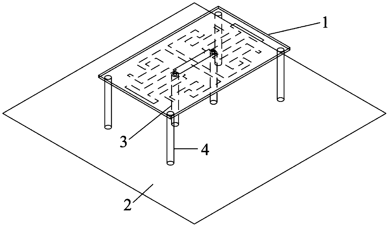
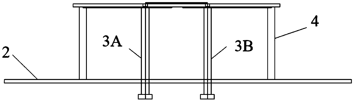
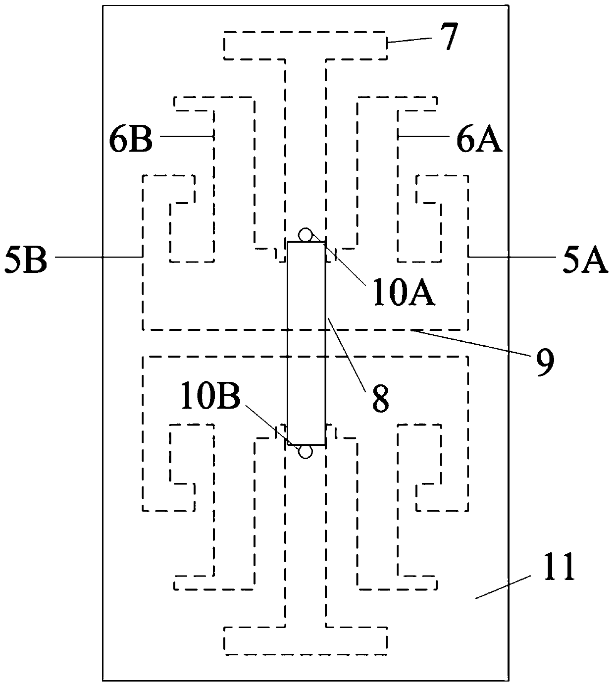
[0034] Such as Figure 1-3 Shown is a structural diagram of a differentially fed tri-band planar antenna, which includes a reflector 2 , a support structure 4 , a first feeder 3A, a second feeder 3B, a dielectric substrate 11 and an antenna radiation unit 1 .

[0035] The reflector is the base and adopts a metal plate;

[0036] The dielectric substrate is fixed on the reflection plate through a supporting structure, and the fixing surface of the supporting structure is the back side of the dielectric substrate;

[0037] The support structure includes M support columns, the support columns are insulating materials, M≥4;

[0038] In this embodiment, the reflective plate 3 is made of aluminum plate; the dielectric substrate 11 is made of high-frequency plate Rogers4350B with a thickness of 0.76 mm and a relative dielectric constant of 3.48; the supporting columns in the supporting structure 4 are made of plastic.

[0039] The dielectric substrate is fixed on the reflector throu...


PUM


Abstract

The invention discloses a differential feeding three-frequency planar antenna. The differential feeding three-frequency planar antenna comprises a reflection plate, a support structure, a dielectric substrate, a first feeder, a second feeder and an antenna radiation unit, wherein the reflection plate is a base, the dielectric substrate is fixedly arranged on the reflection plate by the support structure, the support structure comprises M support posts, the support posts are insulation materials, and the antenna radiation unit is etched on the dielectric substrate and comprises a low-frequencyoscillator, a first medium-frequency oscillator, a second medium-frequency oscillator, a first high-frequency oscillator, a second high-frequency oscillator, a coplanar microstrip line and a microstrip line feeding structure. The differential feeding structure is employed and combined with a planar structure, combination with a differential radio frequency front end can be facilitated, three-frequency working is achieved, and the differential feeding three-frequency planar antenna has the advantages of high gain and stable radiation pattern.

Description

technical field [0001] The invention relates to the field of mobile communication, in particular to a differential feed tri-frequency planar antenna. Background technique [0002] With the rapid development of communication systems in recent decades, people's requirements for communication systems continue to increase. Antennas, as the core components of modern communication systems, also put forward higher and higher requirements. Most traditional antennas use a single-port feed mode. In order to solve the integration of the single-port antenna and the RF front-end, a balun (balun) is usually used to convert the differential signal into a single-port signal and then feed it to the single-port antenna. However, single-port antennas limit the use and popularity of integrated RF front-ends using differential ports. The differential antenna uses two feed ports, which can directly connect the two ports of the antenna to the RF front end of the differential port, thereby improv...

Claims


Application Information

Patent Timeline
Patent Type & Authority Applications(China)
IPC IPC(8): H01Q1/38H01Q1/50H01Q5/10H01Q5/28H01Q5/307H01Q19/10
Inventor 靳贵平曾广洁黎淼兰廖绍伟
Owner SOUTH CHINA UNIV OF TECH
Why Eureka
Try Eureka