Switch reluctance machine sensor redundancy system and automatic switching method

A technology of switched reluctance motor and redundant system, which is applied in the direction of electrical components, electromechanical devices, emergency protection circuit devices, etc., which can solve the problems of motor control phase current imbalance, loud noise, damage, etc., and improve trouble-free operation time, strong anti-interference ability and high protection level

Pending Publication Date: 2019-05-10
北京达科轩传动技术有限公司 +1
View PDF0 Cites 7 Cited by
  • Summary
  • Abstract
  • Description
  • Claims
  • Application Information

AI Technical Summary

Problems solved by technology

However, this sensor still has its own shortcomings: 1. The protection level of the sensor is relatively low, and it is easily affected by dust and rain, and the sensor is easy to age and damage;
[0003] 2. The detection of the position of the motor depends on the machining accuracy of the code disc of the photoel

Method used


Image

  • Switch reluctance machine sensor redundancy system and automatic switching method
  • Switch reluctance machine sensor redundancy system and automatic switching method
  • Switch reluctance machine sensor redundancy system and automatic switching method

Examples


Embodiment 1

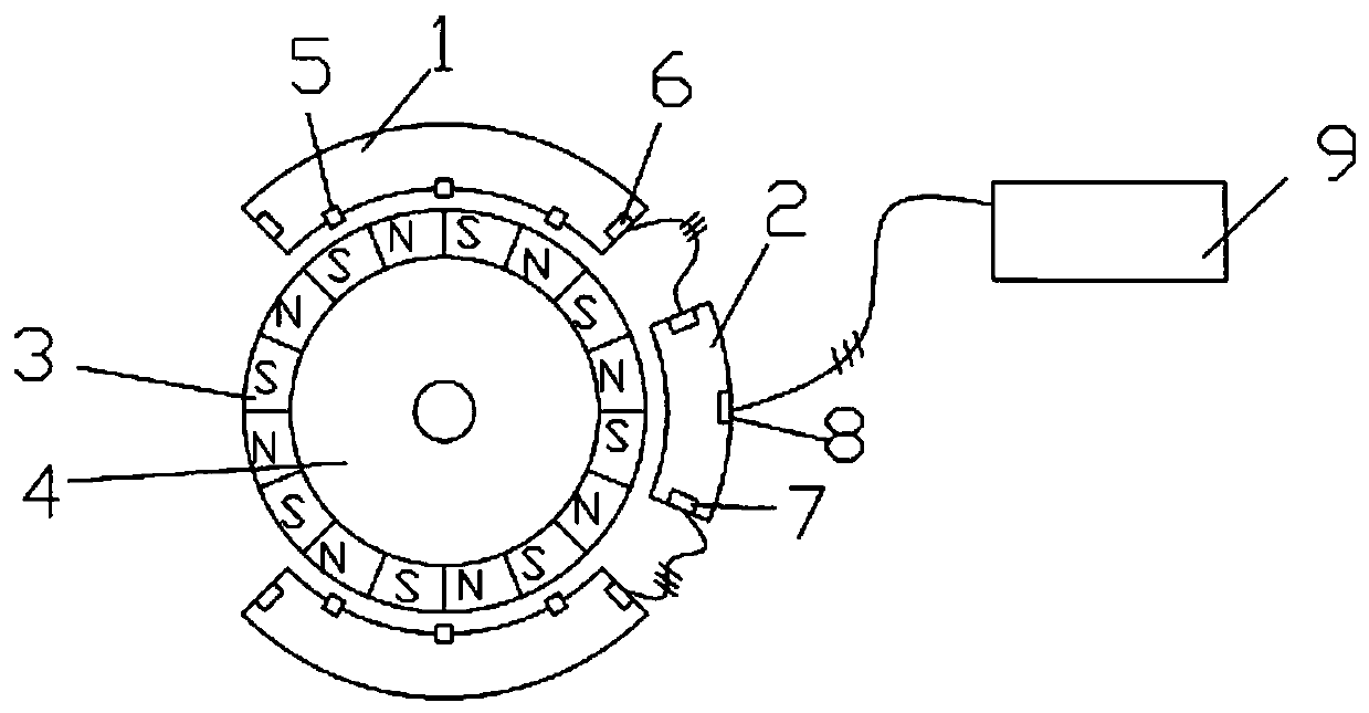
[0039] Embodiment 1: as figure 1 and figure 2 as shown,

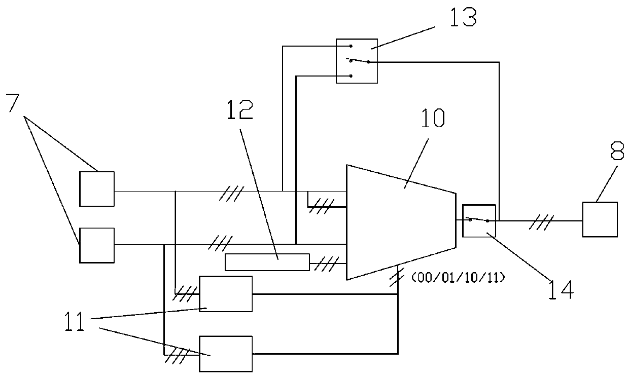
[0040] The system consists of two sensor boards 1 , an interface circuit board 2 , a magnetic ring 3 , and a magnetic ring support 4 . Three Hall sensors 5 and their related signal processing circuits are arranged on the sensor board 1 according to the phases of the motor, and the signal output interface I6 is arranged on the board edge of the sensor board 1 . The sensor board 1 is connected to the interface circuit board 2 through the signal line. The interface circuit board 2 is equipped with two signal input interfaces Ⅰ7 and one signal output interface Ⅱ8. It is equipped with a fault automatic switching circuit, which can realize the failure of one sensor board 1. , automatically switches to the spare sensor board 1. The magnetic ring 3 is radially magnetized according to the motor rotor pole number 16, the sensor board 1 and the interface circuit board 2 are fixed on the motor end cover; the magnetic ring 3 is ...

Embodiment 2

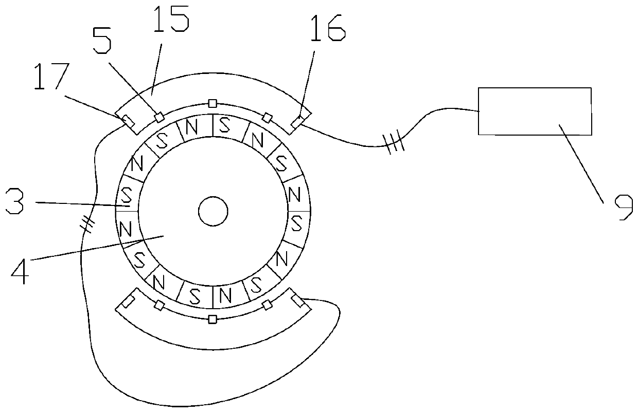
[0046] Embodiment 2: as image 3 and Figure 4 as shown,

[0047] The sensor board 1 and the interface circuit board 2 are integrated into a sensor integration board 15 , so that the signal output interface III 16 on the sensor integration board 15 is connected to the motor control board 9 .

[0048] The system consists of two sensor integrated boards 15 , a magnetic ring 3 , and a magnetic ring support 4 . Three Hall sensors 5 and their related signal processing circuits and switching circuits are arranged on the sensor integrated board 15 according to the phase number of the motor, and the signal output interface III16 and the signal input interface II17 are arranged on the edge of the board. The sensor integrated board 15 is provided with a fault automatic switching circuit, which can automatically switch to the standby sensor board 1 in case of failure of the present sensor board 1 . The magnetic ring 3 is radially magnetized according to the motor rotor pole number 16,...


PUM


Abstract

The invention belongs to the technical field of motor speed regulation, and in particular to a switch reluctance machine sensor redundancy system and an automatic switching method. The switch reluctance machine sensor redundancy system is characterized by comprising a magnet ring supporting member connected with a motor shaft, a magnet ring fixed to the magnet ring supporting member, a plurality of sensor plates located on the periphery of the magnet ring, an interface circuit board connected to the plurality of sensor plates through signal lines, Ns Hall sensors disposed on the sensor plates,signal output interfaces I disposed on the edges of the sensor plates, two signal input interfaces I disposed on both edges of the interface circuit board, and a signal output interface II disposed on the interface circuit board, wherein the signal output interface II is connected with a motor control board. The switch reluctance machine sensor redundancy system provided by the invention has a simple connection with the outside world, high anti-interference ability and small error, is suitable for use in harsh environments, can realize an automatic switching function of faulty sensors, and prolongs the trouble-free running time of a speed regulating system.

Description

technical field [0001] The invention belongs to the technical field of motor speed regulation, and in particular relates to a switch reluctance motor sensor redundancy system and an automatic switching method. Background technique [0002] With the development of power electronics technology and control technology, the speed control technology of switched reluctance motor can develop rapidly. The control of a switched reluctance motor requires knowledge of the rotor position. The reluctance of the magnetic circuit of each phase of the switched reluctance motor changes with the angular position of the rotor. In order to make it work normally, the current of the corresponding phase winding must be turned on or off when the rotor turns to an appropriate position to ensure the current of each phase Synchronized with the corresponding rotor position and always correctly switches the windings of each phase during the rotation of the rotor. Therefore, the angular position detecti...

Claims


Application Information

Patent Timeline
IPC IPC(8): H02K29/08H02H7/00
Inventor 丁金龙田翰辰
Owner 北京达科轩传动技术有限公司
Why Eureka
Try Eureka