Supercharge Your Innovation With Domain-Expert AI Agents!

Oil inlet and outlet opening and closing structure for common-rail high-pressure oil pump

A technology of high-pressure oil pump and opening and closing structure, which is applied in the direction of fuel injection pump, engine components, machines/engines, etc., and can solve the problems of high machining accuracy requirements for split assembly structures, difficulty in ensuring stable sealing accuracy, and unfixed actual sealing surfaces, etc. , to achieve reliable sealing performance, ensure processing accuracy, and improve stability

Inactive Publication Date: 2019-05-14
常州博瑞油泵油嘴有限公司
View PDF0 Cites 0 Cited by
  • Summary
  • Abstract
  • Description
  • Claims
  • Application Information

AI Technical Summary

Problems solved by technology

In the existing technology, the oil pumping components of the common rail fuel injection pump are such as figure 1 As shown in the figure, the control part adopts a split oil inlet and outlet valve structure. This split structure has poor sealing performance and low reliability, and the oil inlet and outlet are sealed with steel balls. In actual work, the steel ball and the corresponding The actual sealing surface between the sealing hole seat surface is not fixed, especially the high-pressure oil outlet control steel ball, there will be continuous impact between the steel ball and the sealing hole seat surface, so that the original sealing pair is damaged, and the sealing accuracy is difficult to guarantee stably. The upper split body assembly structure requires high machining accuracy, low machining efficiency, difficult assembly, and high risk of high pressure leakage

Method used


Image

  • Oil inlet and outlet opening and closing structure for common-rail high-pressure oil pump
  • Oil inlet and outlet opening and closing structure for common-rail high-pressure oil pump
  • Oil inlet and outlet opening and closing structure for common-rail high-pressure oil pump

Examples


Embodiment 1

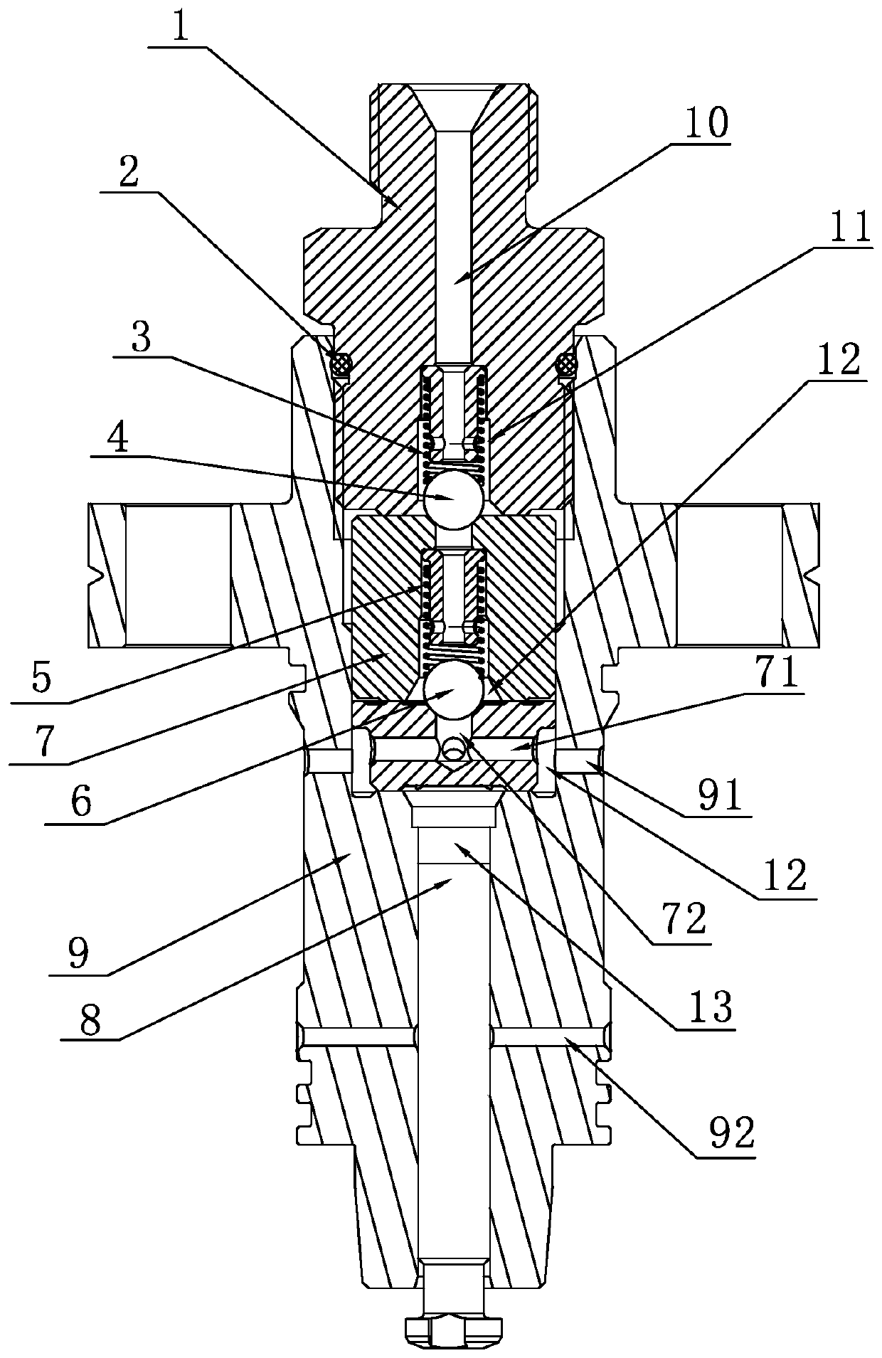
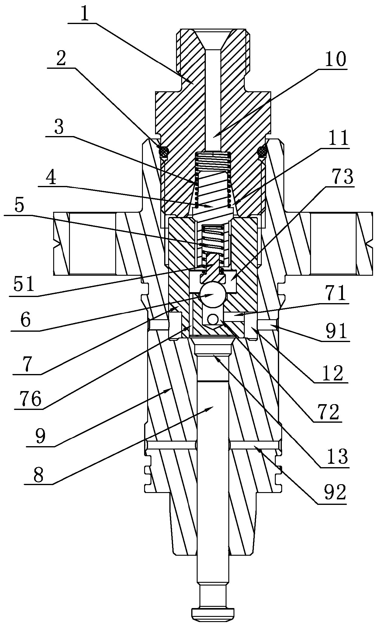
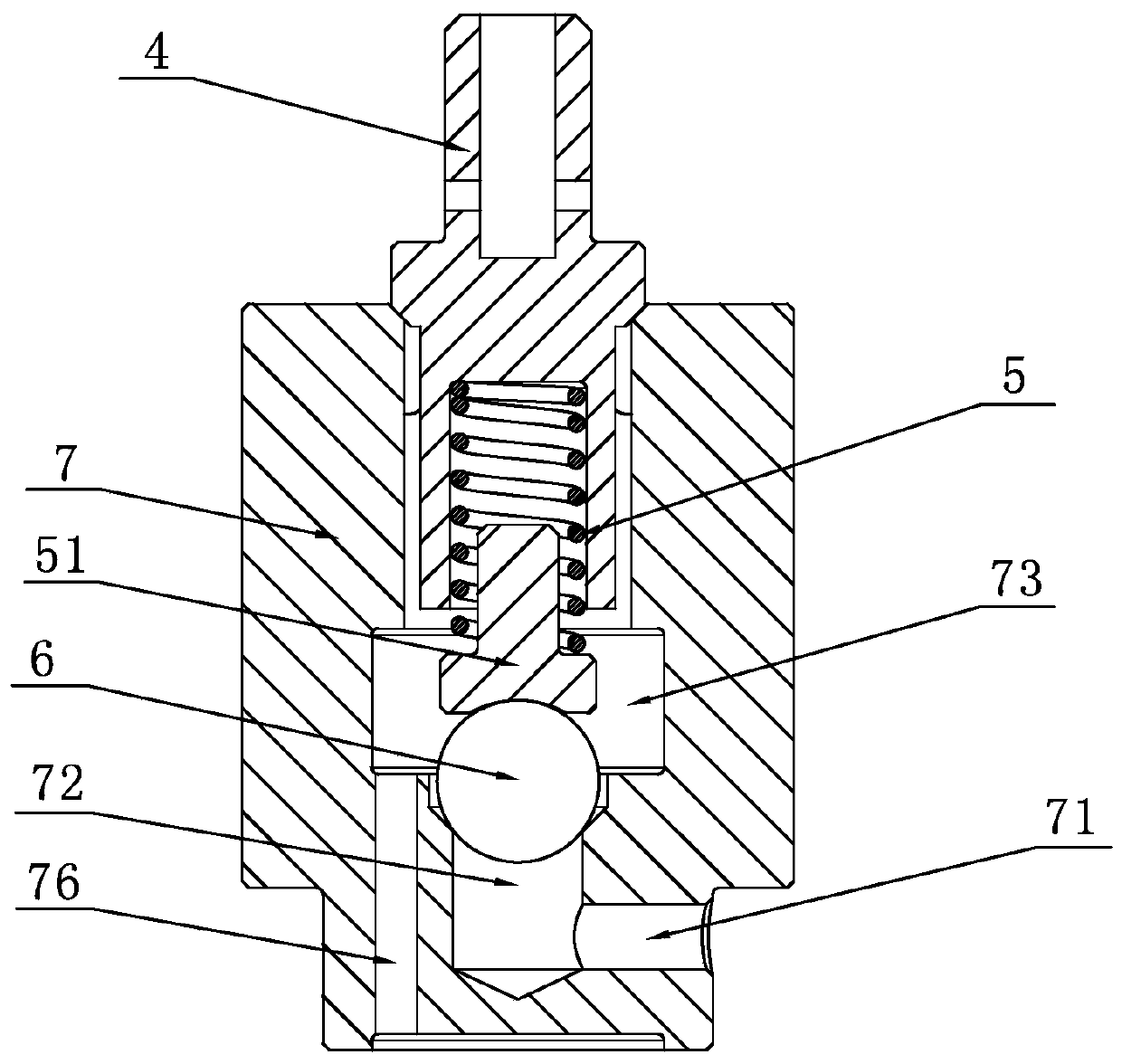
[0026] Embodiment 1: a kind of common rail high-pressure oil pump adopting the present invention, such as Figure 2-Figure 6 As shown, it includes an oil pipe joint 1, a sealing ring 2, an upper spring 3, an upper valve core 4, a lower spring 5, a steel ball 6, a valve seat 7, a plunger 8 and a valve body 9, and it is characterized in that: the upper valve core 4. It is composed of an upper cylinder 41, a sealing cone 42, a guide column 43 and a spring seat hole 44. The sealing cone 42 is arranged between the upper cylinder 41 and the guide column 43, and a sealing cone surface is provided on the sealing cone 42. 45. An axial oil inlet groove 46 is provided on the guide post 43, and the spring seat hole 44 is set at the center of the guide post 43. The diameter of the spring seat hole 44 is equivalent to the outer diameter of the lower spring 5, and the upper cylinder 41 is set on the upper In the inner hole of the spring 3, a central oil outlet hole 47 is provided in the cent...


PUM


Abstract

The invention provides an oil inlet and outlet opening and closing structure for a common-rail high-pressure oil pump. The oil inlet and outlet opening and closing structure comprises an upper valve element, a lower spring, a lower valve element, a valve seat, a plunger piston and a pump body, the upper valve element is composed of an upper column body, a sealing cone, a guiding column and a spring seat hole, and the sealing cone is matched with the conical surface of an upper port of the valve seat in a sealed mode; the valve seat is of an integral structure, and comprises a transverse oil inlet port, a center oil inlet port, an oil storage cavity, a center oil outlet port, the sealing conical surface and a vertical oil inlet port, the sealing conical surface is arranged at the upper opening end of the central oil outlet port, the transverse oil inlet port communicates with the center oil inlet port, the vertical oil inlet port is formed between the oil storage cavity and a reserved oil cavity, and the oil storage cavity communicates with the reserved oil cavity through the vertical oil inlet port. An oil inlet part adopts a spherical sealing structure, an oil outlet part adopts aconical surface sealing structure, the valve seat with the integral structure can prevent leakage, processing and assembly are convenient, the qualified rate of finished products is high, and the service life is long.

Description

Technical field: [0001] The patent of the present invention relates to an electronically controlled common-rail fuel injection system for diesel engines, in particular to a high-pressure common-rail fuel injection pump. Background technique: [0002] With the implementation of high-standard emission requirements for diesel engines, the rail pressure requirements of high-pressure common rail systems have also increased. In order to meet the oil supply efficiency requirements of high-rail pressure pumps, the product must have extremely high requirements for sealing and fast oil intake. , high oil outlet pressure, fast response, long service life, high reliability, etc., and at the same time ensure low processing and assembly costs, and a high pass rate for one-time assembly of finished products. In the existing technology, the oil pumping components of the common rail fuel injection pump are such as figure 1 As shown in the figure, the control part adopts a split oil inlet an...

Claims


Application Information

Patent Timeline
Patent Type & Authority Applications(China)
IPC IPC(8): F02M59/46F02M59/48
Inventor 汤志明汤曌杨俊召谈旭扬王志康陈晔景小华
Owner 常州博瑞油泵油嘴有限公司
Features
  • R&D
  • Intellectual Property
  • Life Sciences
  • Materials
  • Tech Scout
  • Unparalleled Data Quality
  • Higher Quality Content
  • 60% Fewer Hallucinations
Learn More