
Electrical control device and method for pressure oil pump

An electrical control device and pump control technology, applied in pump control, liquid variable capacity machinery, machine/engine, etc., can solve the problems of pipeline oil shock, affecting the service life of the oil supply pump, not considering phase sequence protection measures, etc. The effect of reducing shock and noise, improving the quality of oil supply, and improving the quality of power supply

Pending Publication Date: 2019-05-14
CHINA YANGTZE POWER
View PDF0 Cites 4 Cited by
  • Summary
  • Abstract
  • Description
  • Claims
  • Application Information

AI Technical Summary

Problems solved by technology

[0003] (1) The pressure oil pump consumes a lot of energy. Due to its long-term full-pressure and power-frequency operation mode, it causes energy waste and aggravates the wear and tear of the pump.
[0004] (2) When the oil pump is started, oil shock occurs in the pipeline, resulting in large shaking impact and noise, which affects the service life of the oil supply pump
When the pressure oil pump is started, a large current impact is generated, which poses certain risks to the oil pump and the entire control system, and there is no overcurrent protection measure
[0005] (3) The phase sequence protection measures are not considered in the design of the pressure oil pump control method, which may easily cause the oil pump to reverse and fail to load
When the pressure oil pump is overhauled, it is easy to reverse the phase sequence, which will cause the pump to turn incorrectly and the motor to reverse. When the pressure oil pump starts to load, it will not be loaded normally. The oil pump will fail to load. If the oil pressure is low, it will cause the unit to stop due to low oil pressure.
[0006] (4) During the design of the oil pump control method, no consideration was given to detecting the voltage and current at the inlet end of the oil pump motor power supply

Method used


Image

  • Electrical control device and method for pressure oil pump
  • Electrical control device and method for pressure oil pump
  • Electrical control device and method for pressure oil pump

Examples


Embodiment Construction

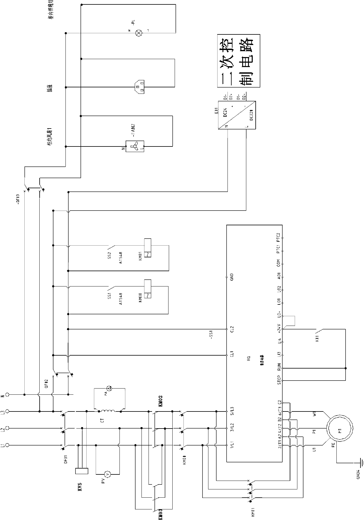
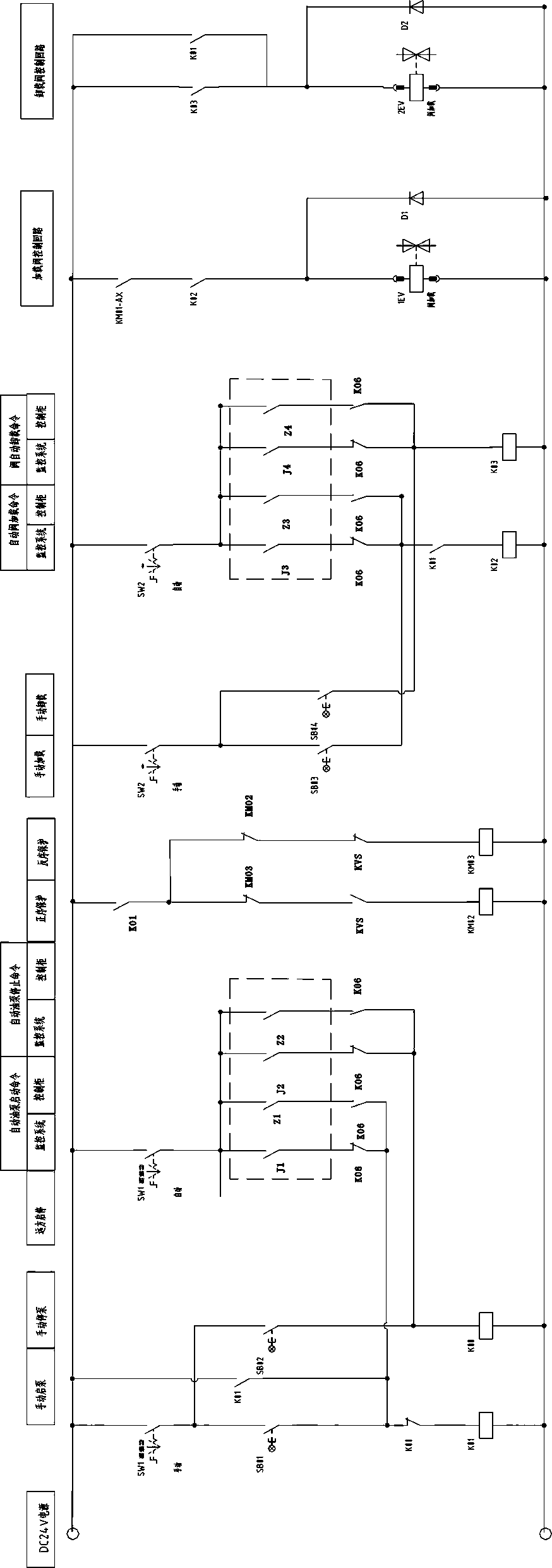
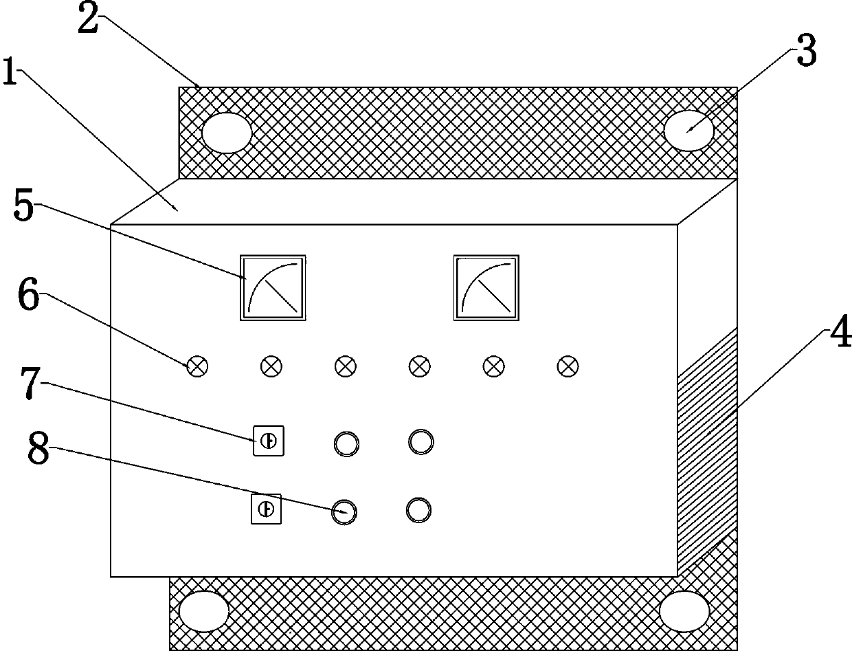
[0046] An electrical control device for a pressure oil pump, comprising a primary circuit, a secondary circuit and an auxiliary control circuit.

[0047] The primary circuit includes circuit breaker QF01, phase sequence protection device KVS, positive sequence contactor KM02, reverse sequence contactor KM03, main contactor KM00, bypass contactor KM01, soft starter RQ;

[0048] The secondary circuit includes start button SB01, stop button SB02, load button SB03, unload button SB04, pump start relay K01, pump stop relay K00, load relay K02, unload relay K03, positive sequence contactor KM02, reverse sequence contactor KM03, loading valve 1EV, unloading valve 2EV, start-stop switching handle SW1, loading and unloading switching handle SW2, control cabinet fault point relay K06;

[0049] The three phases L1, L2, and L3 are respectively connected to the phase sequence protection device KVS to detect whether the phase sequence is correct;

[0050] Any two phases are connected in pa...


PUM


Abstract

The invention relates to an electrical control device and method for a pressure oil pump. The electrical control device comprises a primary loop and a secondary loop. The primary loop comprises a circuit breaker QF01, a phase sequence protection device KVS, a positive sequence contactor KM02, a reverse sequence contactor KM03, a main contactor KM00, a bypass contactor KM01 and a soft starter RQ; and the secondary loop comprises a start button SB01, a stop button SB02, a loading button SB03, an unloading button SB04, a pump-starting relay K01, a pump-stopping relay K00, a loading relay K02, anunloading relay K03, a positive sequence contactor KM02, a reverse sequence contactor KM03, a loading valve 1EV, an unloading valve 2EV, a start-stop switching handle SW1, a loading-unloading switching handle SW2 and a control cabinet fault point relay K06. According to the electrical control device and method for the pressure oil pump, the control mode for the pressure oil pump of a speed regulator oil pressure device is technically optimized and studied so as to improve the operation reliability of the pressure oil pump.

Description

technical field [0001] The invention relates to the technical field of pressure oil pump control, in particular to an electrical control device and method for a pressure oil pump. Background technique [0002] The pressure oil pump is an important electrical equipment in most industrial production and daily life. The pressure oil pump of the governor oil pressure device is an important auxiliary equipment of the power plant. It plays a decisive role in maintaining the oil pressure of the pressure oil tank and ensuring the reliable operation of the governor. high reliability. In actual production, the control system of the pressure oil pump has the following defects in design and operation: [0003] (1) The pressure oil pump consumes a lot of energy. Due to its long-term operation mode of full pressure and power frequency, it causes energy waste and aggravates the wear and tear of the pump. [0004] (2) When the oil pump is started, oil shock occurs in the pipeline, resulti...

Claims


Application Information

Patent Timeline
Patent Type & Authority Applications(China)
IPC IPC(8): F04B49/06F04B49/10
Inventor 张官祥童绪林杨廷勇王桥智何宏江蒋承峰崔敏张东峰王永伟詹福伟
Owner CHINA YANGTZE POWER
Learn More