Impression-free linkage type self-material-returning cutter die

A linkage and material return technology, which is applied in metal processing and other directions, can solve the problems that cannot meet the needs of product performance and appearance, and is fragile, so as to improve product yield and production efficiency, facilitate processing, and compact mold structure design. Effect

Inactive Publication Date: 2019-05-17
SHENZHEN BSC TECHNOLOGY CO LTD
View PDF5 Cites 3 Cited by
  • Summary
  • Abstract
  • Description
  • Claims
  • Application Information

AI Technical Summary

Problems solved by technology

This kind of protective auxiliary material not only has a thicker product thickness, but also takes into account the requirements of high light transmittance (average light transmittance ≥ 93%), and materials such as high transmittance film are very easy to wear because of the special coating treatment. The disadvantages of broken, the traditional die-cutting industry, the use of ordinary engraving knife die cutting, the use of the die cavity pad return foam, when punching, the product and the return foam are squeezed into the die cavity, punching During the rising process of the knife die after cutting, the returned foam will eject the product. Due to the attenuation of the rebound of the foam, the punching process requires a large amount of release agent to cause extrusion marks and oil stains on the surface of the high-permeability film, which basically cannot meet the requirements of the product. Performance and Appearance Requirements

Method used


Image

  • Impression-free linkage type self-material-returning cutter die
  • Impression-free linkage type self-material-returning cutter die
  • Impression-free linkage type self-material-returning cutter die

Examples


Embodiment Construction

[0017] In order to make the purpose, technical solutions and advantages of the embodiments of the present invention clearer, a clear and complete description will be made below in conjunction with the technical solutions in the embodiments of the present invention. Obviously, the described embodiments are part of the embodiments of the present invention, and Not all examples. Based on the embodiments of the present invention, all other embodiments obtained by persons of ordinary skill in the art without making creative efforts belong to the protection scope of the present invention.

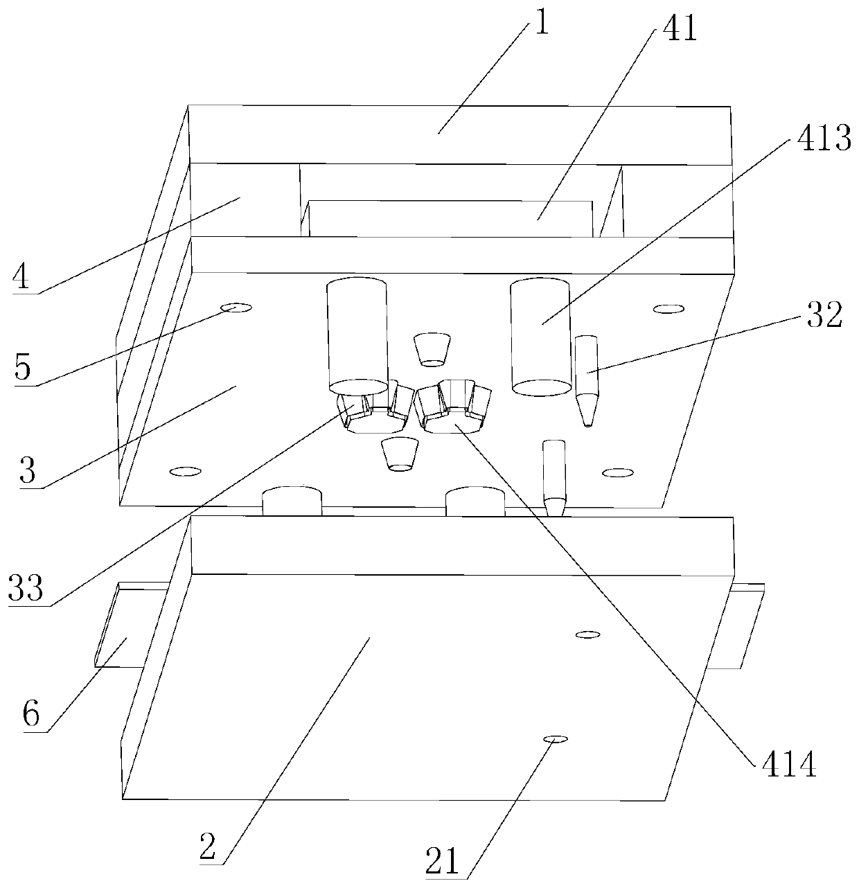
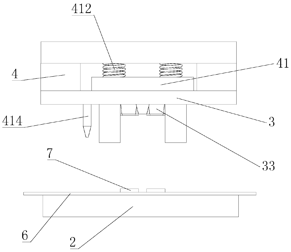
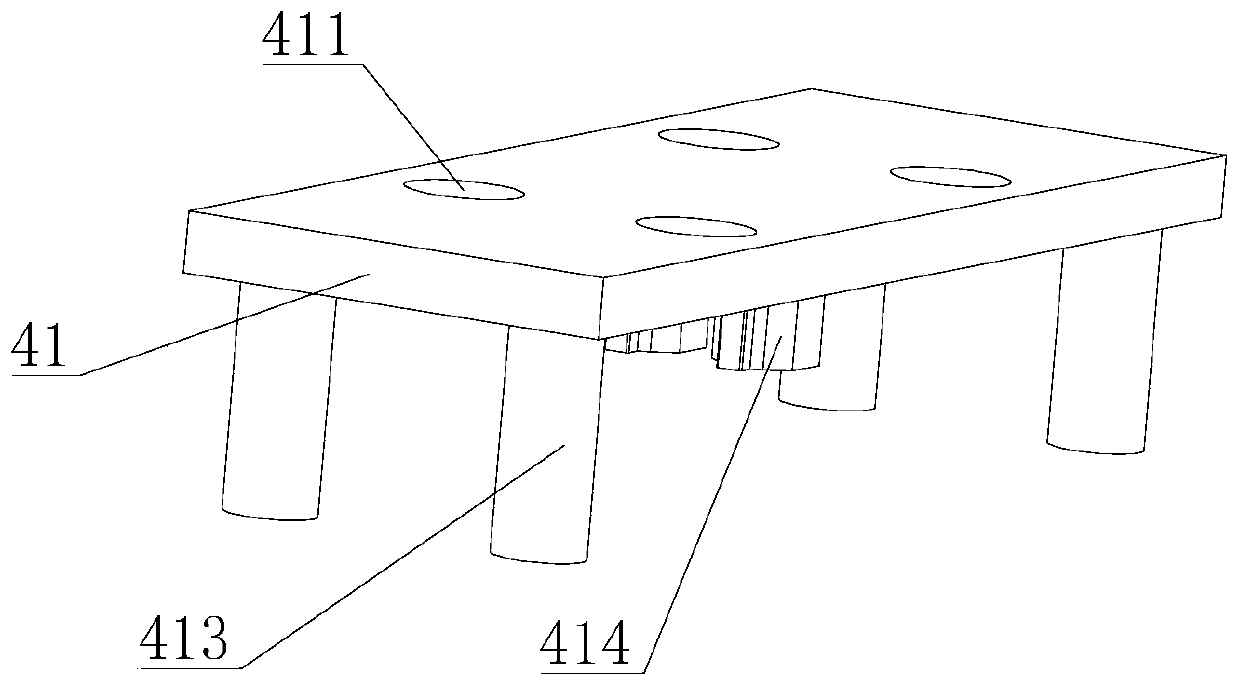
[0018] like Figure 1-Figure 4 Shown: a non-embossing linkage self-returning die, including an upper template 1, a lower template 2 and a cutter template 3, two spacers 4 are arranged between the upper template 1 and the knife template 3, and two spacers 4 are respectively installed on both sides of the cutting board 3 in the length direction, the upper template 1, the spacer 4 and the cutting b...


PUM


Abstract

The invention relates to an impression-free linkage type self-material-returning cutter die comprising an upper die plate, a lower die plate and a cutter die plate. Two cushion blocks are arranged between the upper die plate and the cutter die plate and are installed at the positions, close to edges of the front side and the rear side of the cutter die plate, of the cutter die plate correspondingly. The upper die plate, the cushion blocks and the cutter die plate are connected through bolts. Through holes are formed in the cutter die plate. A material returning plate is arranged between the two cushion blocks. Spring installation holes are formed in the material returning plate. Material returning springs are installed on the spring installation holes. Guide columns are arranged on the portions, close to the left side and the right side, on the lower face of the material returning plate. Material returning columns are arranged at the middle portion positions of the lower face of the material returning plate. The through holes are formed in the cutter die plate, positioning needles are arranged on the lower face of the cutter die plate, cutter points are arranged on the lower face of the cutter die plate, and positioning holes corresponding to the positions of the positioning needles are formed in the lower die plate. In the rising process of the upper die plate, the guide columns are also separated from the upper die plate, and the material returning columns are pushed by the springs to eject out products downwards.

Description

technical field [0001] The invention relates to the technical field of a material-returning die, and more specifically relates to a non-embossing linkage type self-returning die. Background technique [0002] With the development of the current industry, the cameras used in digital camera products such as mobile phones, digital cameras, and tablet computers are also developing in the direction of ultra-telephoto focus, ultra-high pixels, and high integration. For high-precision components such as cameras, how to ensure their protection during the production process, transportation, and complete machine assembly is particularly important. This kind of protective auxiliary material not only has a thicker product thickness, but also takes into account the requirements of high light transmittance (average light transmittance ≥ 93%), and materials such as high transmittance film are very easy to wear because of the special coating treatment. The disadvantages of broken, the trad...

Claims


Application Information

Patent Timeline
Patent Type & Authority Applications(China)
IPC IPC(8): B26F1/44B26D7/18
Inventor 唐欢陈国华
Owner SHENZHEN BSC TECHNOLOGY CO LTD
Why Eureka
Try Eureka