Preparation method and production mould for light-transmitting concrete

A light-transmitting concrete and manufacturing method technology, applied in the direction of manufacturing tools, ceramic molding machines, etc., can solve the problems of easy bending of optical fibers, difficult positioning of optical fibers, and floating, etc., to achieve the effects of improving production efficiency, ensuring regularity, and saving time

Inactive Publication Date: 2019-05-17
湖南恒盛瑞通新型建材有限公司
View PDF7 Cites 8 Cited by
  • Summary
  • Abstract
  • Description
  • Claims
  • Application Information

AI Technical Summary

Problems solved by technology

Although this method is convenient in technology, due to the lack of a mold that can fix the fiber after weaving firmly, the position of the fiber will be affected when the cement slurry is poured, causing the fiber to be easily bent, floating, sliding and misplaced, making the positioning of the fiber difficult and uneven. Distributed in the cement matrix, affecting the light transmission effect and decoration of light-transmitting concrete

Method used


Image

  • Preparation method and production mould for light-transmitting concrete
  • Preparation method and production mould for light-transmitting concrete

Examples


Embodiment 1

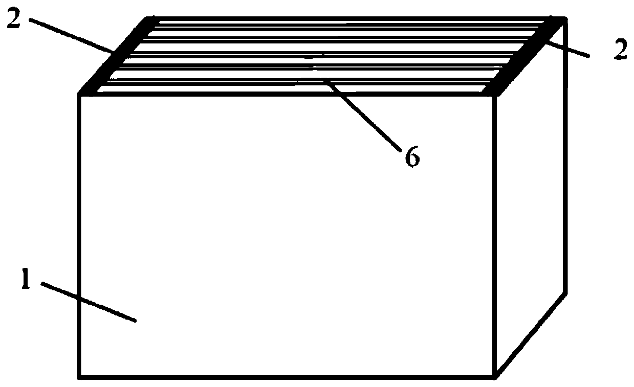
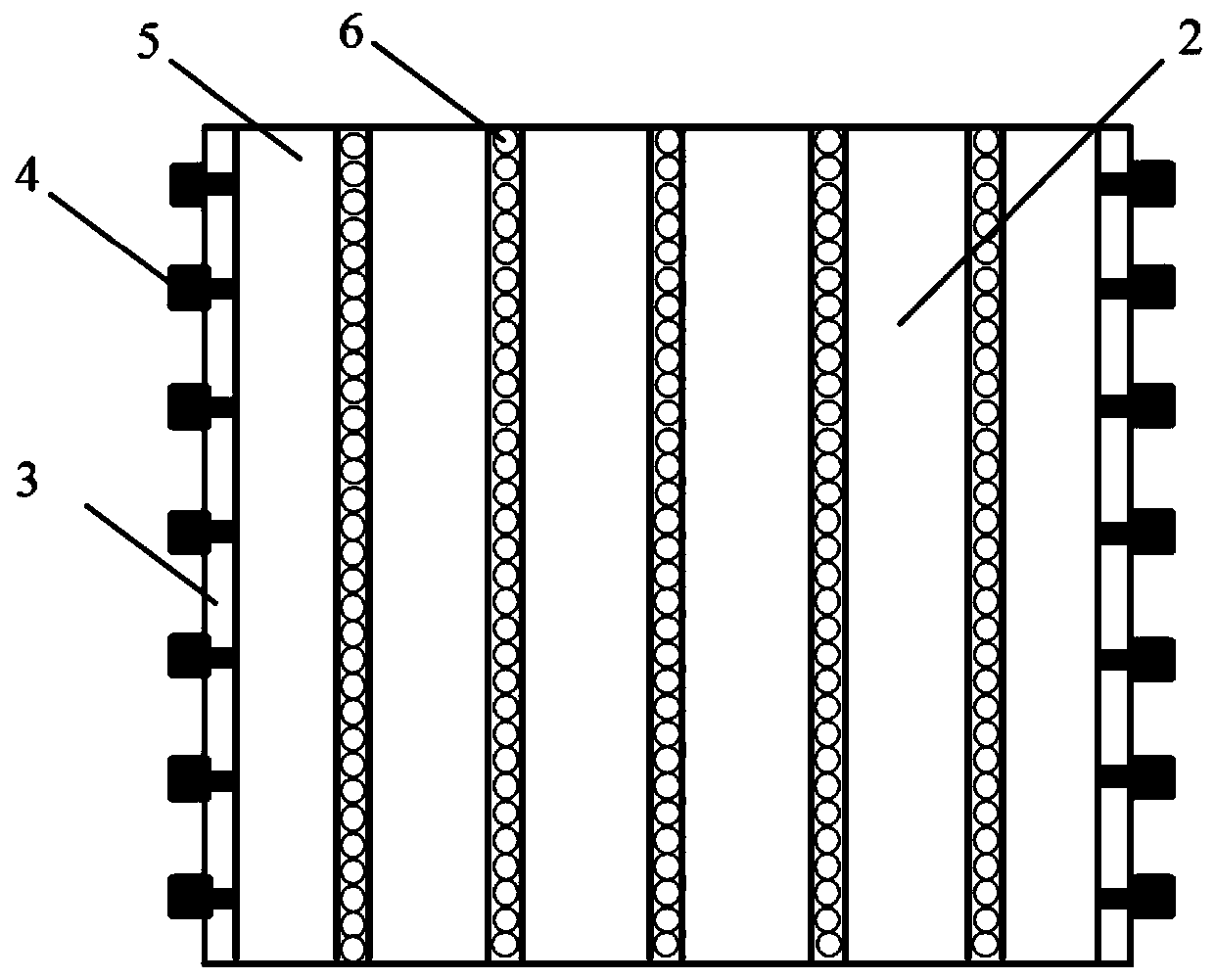
[0027] Such as figure 1 As shown, the embodiment of the present invention provides a production mold 1 for light-transmitting concrete. The mold 1 includes a bottom plate, two templates 2 and four side plates. Two formworks 2 are arranged close to the insides of the left and right side panels to form a concrete molding area. Such as figure 2 As shown, the template 2 is symmetrically provided with several pressing sheets 5, each pressing sheet compresses one layer of optical fiber, one pressing sheet, one layer of optical fiber, and so on, filling the entire mold. The pressing piece is fixed by bolts 4, and the bolt 4 passes through the steel frame pressing strips 3 at both ends of the formwork to fix the pressing piece 5 on the formwork 2. The optical fiber is compressed and fixed between the pressing sheets 5 .

[0028] The two templates 2 are arranged symmetrically, and the optical fibers 6 are arranged in layers between the pressing sheets 5 , and the thickness of the p...

Embodiment 2

[0030] The difference from Embodiment 1 is that two formworks 2 are arranged between the left and right side panels, and the distance between the two formworks 2 is greater than one-third of the distance between the left and right side panels, forming three concrete forming areas. The inner sides of the left and right side plates are provided with grooves corresponding to the positions of the optical fibers, and the ends of the optical fibers are fixed in the grooves. The width of the groove is 0.3-0.6 mm larger than the diameter of the optical fiber.

Embodiment 3

[0032] (1) Cement paste, including water, sand, cement, fly ash and water reducer, wherein the mass ratio of water, sand, cement, fly ash and water reducer is 301:1066:544:293:8.37 , the fluidity of cement paste is ≥250mm, and the density of cement mortar is 2.0-2.2g / cm 3 . The cement is P.O 42.5 grade ordinary Portland cement; the water reducer is a polycarboxylate water reducer, and the water reducing rate of the polycarboxylate water reducer is ≥ 25%; the fly ash is class F class II ash; River sand is sieved through a 2.36mm square hole sieve to remove the above part and the part below the 0.075mm square hole sieve, and the mud content is ≤1%.

[0033] (2) The optical fiber is a plastic optical fiber with a density of 0.8-1.5g / cm 3 .

[0034] (3) Make light-transmitting concrete according to the following methods:

[0035] 1) Fix the optical fiber in the mold, and it is advisable to control the fluidity of the matrix at about 300mm, so that the matrix and the optical fi...


PUM

PropertyMeasurementUnit
densityaaaaaaaaaa
densityaaaaaaaaaa
volume ratioaaaaaaaaaa

Abstract

The invention provides a preparation method and a production mould for light-transmitting concrete. The production mould is of a rectangular structure, and comprises a bottom plate, two moulding boards and four side plates, wherein the moulding boards are perpendicular to the bottom plate, and are fixedly arranged between the left and right side plates; and a plurality of pressure sheets are arranged on the moulding boards for fixing optical fibers. The preparation method for the light-transmitting concrete comprises the following steps: fixing the optical fibers in the mould; injecting cementslurry into the mould to perform vibrating; de-moulding after curing the cement slurry to obtain light-transmitting concrete primary products; cutting the primary product optical fibers, and grinding, polishing, and performing dust-proof, water-roof and anti-fouling treatment to obtain the light-transmitting concrete finished products. The mould provided by the invention can fix the optical fibers very well, and guarantees regularity of positions of optical fibers in the light-transmitting concrete finished products which can meet requirements of attractive and light-transmitting effects of the light-transmitting concrete. The method provided by the invention can greatly save optical fiber arranging time while manufacturing light-transmitting concrete, and improves production efficiency.

Description

technical field [0001] The invention relates to the technical field of new concrete materials, in particular to a method for making light-transmitting concrete and a production mold thereof. Background technique [0002] After more than a century of research and practice, concrete technology has achieved rapid development, and concrete materials have become the engineering materials with the largest amount and the widest application range in today's engineering construction. With the progress of society, people's demands on the functions of concrete materials are becoming more and more diversified. In order to not only meet the thermal insulation requirements of the building, but also transmit light and save energy, the Hungarian architect Aron Losonczi invented the light-transmitting concrete, that is, many optical fibers are implanted into the concrete, and the light is transmitted by the optical fibers to form light-transmitting concrete. The wall made of light-transmitt...

Claims


Application Information

Patent Timeline
Patent Type & Authority Applications(China)
IPC IPC(8): B28B1/04B28B1/093B28B23/00C04B28/00
Inventor 李长双陈华湘李胤吴海浪
Owner 湖南恒盛瑞通新型建材有限公司
Why Eureka
Try Eureka