A wave box girder

A wave box and box girder technology, applied in bridges, buildings, building components, etc., can solve the problems of building stability and seismic performance damage, reducing building integrity, and poor bonding, so as to enhance the ability to resist collapse , Inhibition of local buckling or overall instability, and the effect of reducing workload

Active Publication Date: 2020-01-14
JIANGNAN UNIV
View PDF6 Cites 2 Cited by
  • Summary
  • Abstract
  • Description
  • Claims
  • Application Information

AI Technical Summary

Problems solved by technology

Therefore, if prefabricated box girders can be used to replace steel-concrete composite beams, it will be able to greatly solve the problems of complex connection structure of existing steel-concrete composite beam joints, cumbersome splicing and formwork construction
[0005] However, the existing prefabricated box girders still have the following major problems: first, the existing prefabricated box girders are almost all-inclusive, although the connection between the prefabricated box girders of this form and the column structure It is relatively simple and well connected, but there is a big problem with the connection between the floor and the concrete part of the floor and the outer steel part of the prefabricated box girder can not be well bonded; second, in the earthquake environment, Due to the existence of transverse shear force, the outsourcing steel and concrete of the prefabricated box girder are prone to separation, especially the bottom plate part of the outsourcing steel. Force, easier to separate from concrete
[0006] The above problems have greatly reduced the integrity of the building and caused damage to the stability and seismic performance of the building.

Method used


Image

  • A wave box girder
  • A wave box girder
  • A wave box girder

Examples


Embodiment 1

[0050] Embodiment 1: A corrugated box girder

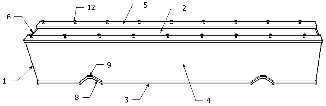
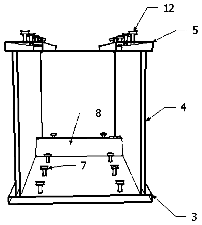
[0051] Such as Figure 1-3 , a corrugating box girder comprising a steel frame 1 and rectangular concrete 2 filled inside the steel frame 1;

[0052] The steel skeleton 1 includes a corrugated floor 3, two webs 4 distributed along the length direction of the beam and vertically connected to the corrugated floor 3, and two webs 4 parallel to the corrugated floor 3 and vertically connected to the two webs 4 respectively. Cover plate 5, and two partition plates 6 located at both ends of the box girder and vertically connected to the corrugated bottom plate 3, web plate 4 and cover plate 5 at the same time;

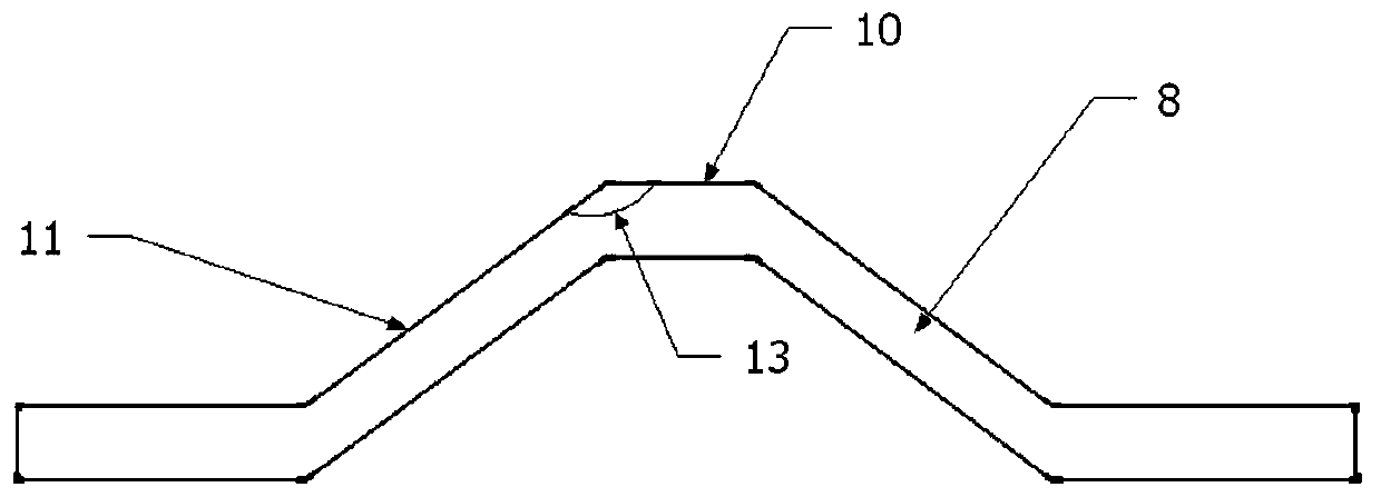
[0053] The wave bottom plate 3 is connected with a number of first bolts 7 built into the rectangular concrete 2 and the wave bottom plate 3 is provided with an inverted "U"-shaped wave 8; the inverted "U"-shaped wave 8 is not in contact with the The plates 4 are connected; the inverted "U" wave 8 is separated from the rectangu...

Embodiment 2

[0067] Embodiment 2: A construction method of corrugated box girder

[0068] Specific steps are as follows:

[0069] (1) Perform corrugation on the corrugated bottom plate 3 and arrange the first bolts 7 on the corrugated bottom plate 3, cut the web 4 according to the design of the inverted “U” wave 8, and cut the web 4 Vertically welded on both sides of the corrugated bottom plate 3, no welding is performed at the 8 inverted "U"-shaped waves, the cover plate 5 is vertically welded on the top of the web plate 4, and the partition plate 6 is vertically welded to the corrugated bottom plate 3 and the web plate 4. The two ends of the cover plate 5 obtain the steel skeleton 1;

[0070] (2) Cover the non-stick film 9 on the inverted "U" wave 8, and pour rectangular concrete 2 inside the steel skeleton 1 to obtain the corrugated box girder.

Embodiment 3

[0071] Example 3: Detection of a corrugated box girder

[0072] Specific steps are as follows:

[0073] Use C40 ordinary concrete as the material of the rectangular concrete, Q345 steel as the material of the steel skeleton, select the first bolt and the second bolt of the model of M20*90 outer hexagonal hot-dip galvanized bolts, and select the non-stick film of plastic material, according to the embodiment 1-2. Prepare a corrugated box girder.

[0074] The span of the corrugated box girder is 5m, and the section size is 250mm×500mm; the section size of the corrugated bottom plate is 250mm×10mm; the section size of the web plate is 480mm×6mm; the size of the cover plate is 75mm×8mm; the size of the partition It is 200mm×500mm×10mm; there are two inverted “U”-shaped waves on the corrugated bottom plate, and the distance between the center of one inverted “U”-shaped wave and the closer partition is one-fifth of the beam length , the distance between another inverted "U" wave a...


PUM


Abstract

The invention discloses a corrugated box beam, and belongs to the technical fields of construction and structural engineering. A corrugated bottom plate of the corrugated box beam provided by the invention bends and corrugates at inflection points near beam-column joints to form inverted U-shaped wavy protrusions, and the inverted U-shaped wavy protrusions deform greatly in the process of straightening under load, so that the deformation capacity of the corrugated box beam under earthquake action is greatly increased, and the collapse resistance capacity of the corrugated box beam under largeearthquakes is greatly enhanced; in addition, corrugated parts of the corrugated box beam are covered with non-stick films, so that the corrugated box beam is not bonded to concrete locally, and no affect is caused on the deformation of the inverted U-shaped wavy protrusions, the deformation capacity of the corrugated box beam under the earthquake action is further increased, and the collapse resistance capacity of the corrugated box beam under the large earthquakes is greatly enhanced.

Description

technical field [0001] The invention relates to a corrugated box girder, which belongs to the technical field of architecture and structural engineering. Background technique [0002] Steel-concrete composite structure is the fifth largest type of structure developed after wood structure, masonry structure, reinforced concrete structure and steel structure. Steel-concrete composite beam is a kind of steel-concrete composite structure, which refers to the steel-concrete composite beam composed of I-beam or H-shaped steel and concrete filled in the flanges on both sides. The material properties of concrete can effectively improve the bearing capacity, ductility and seismic performance of composite beams. Specifically, the concrete in the flanges on both sides of composite beams is in a three-dimensional stress state due to the wrapping of flanges and webs, which has a certain restraint effect. , the profile steel of the composite beam can effectively restrain the occurrence o...

Claims


Application Information

Patent Timeline
Patent Type & Authority Patents(China)
IPC IPC(8): E01D2/04E04C3/293
Inventor 邹昀周渊李天祺张世钧周虹
Owner JIANGNAN UNIV
Why Eureka
Try Eureka