Hydraulic conveying device for hydraulic engineering, with long service life
What is Al technical title?
Al technical title is built by PatSnap Al team. It summarizes the technical point description of the patent document.
A technology of hydraulic conveying and water conservancy engineering, applied in drinking water installations, water supply installations, water/sewage treatment and other directions, can solve the problems of impeller wear, damage to equipment, shorten the service life of water pumps, etc., to ensure safe use, improve practicability, The effect of prolonging the service life
Inactive Publication Date: 2019-05-17
邹红 +4
View PDF7 Cites 2 Cited by
Summary
Abstract
Description
Claims
Application Information
AI Technical Summary
This helps you quickly interpret patents by identifying the three key elements:
Problems solved by technology
Method used
Benefits of technology
Problems solved by technology
[0003] However, in the process of conveying water, the water contains some sundries such as branches and gravels. These sundries enter the water pump and contact the impeller in the pump body, causing friction, which is easy to cause wear of the impeller, thereby shortening the service life of the water pump, seriously It can also damage the equipment and reduce the practicality of existing hydraulic conveying devices
Method used
Image
Click on the blue label to locate the original text in one second.
Reading with bidirectional positioning of images and text.
Examples
Embodiment Construction
[0024] The present invention is described in further detail now in conjunction with accompanying drawing. These drawings are all simplified schematic diagrams, which only illustrate the basic structure of the present invention in a schematic manner, so they only show the configurations related to the present invention.
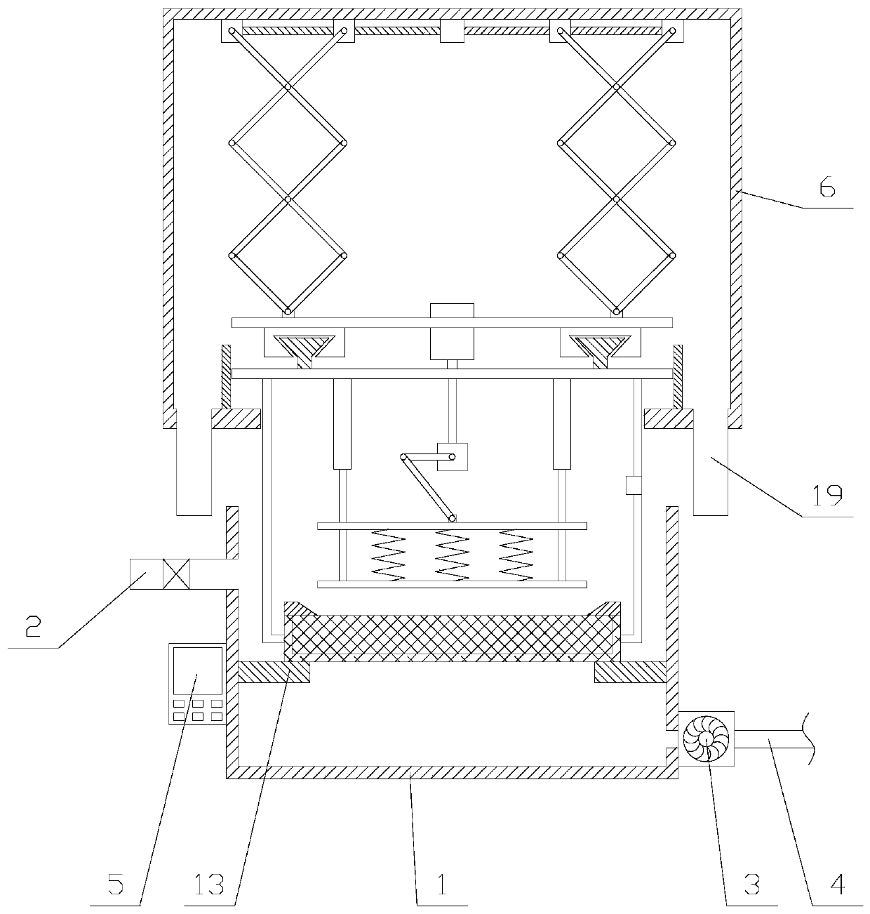
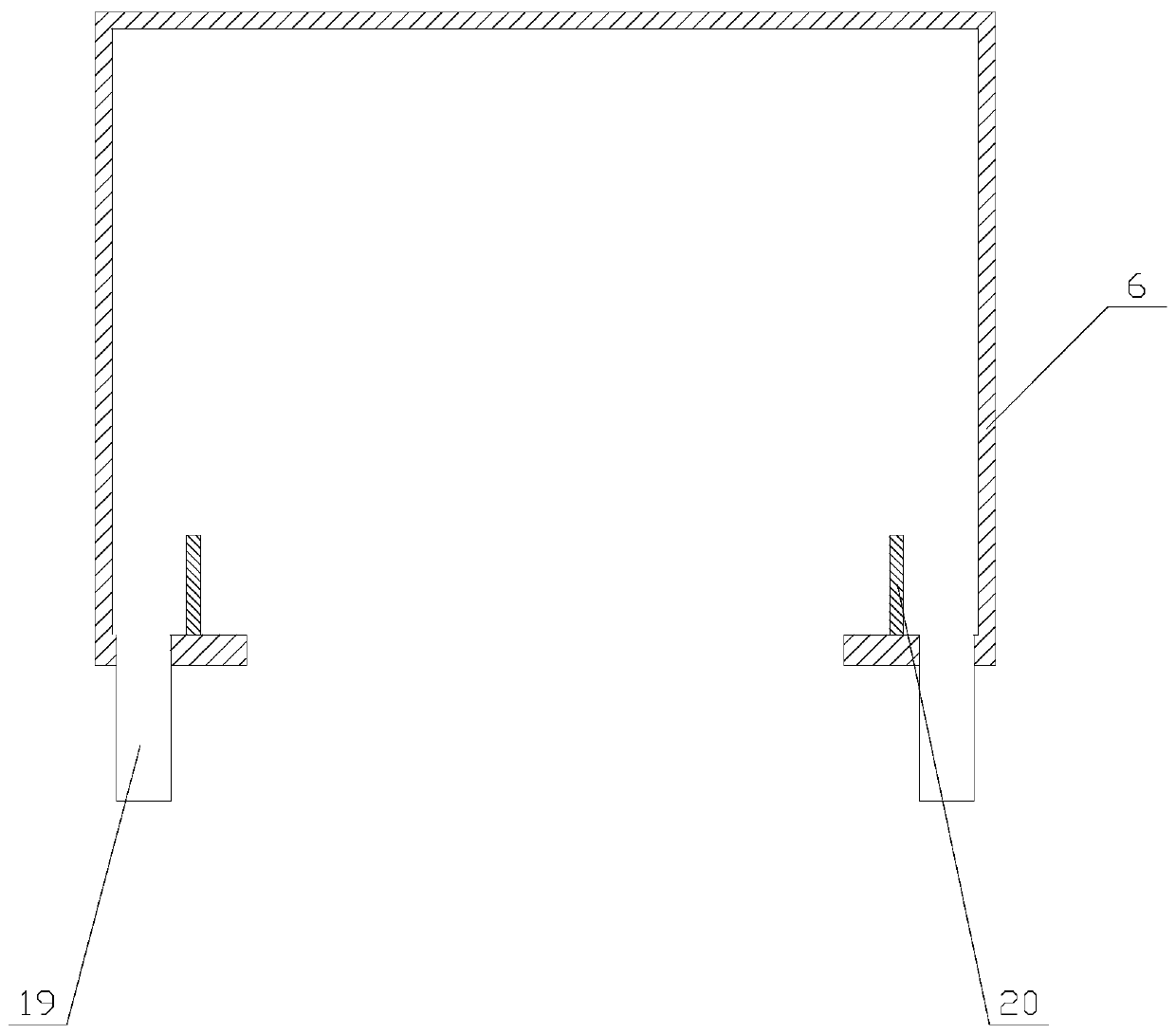
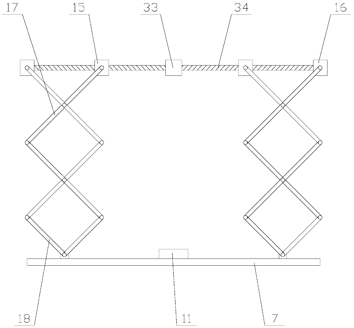
[0025] Such as figure 1 As shown, a hydraulic conveying device with a long service life for water conservancy projects, including a pool 1, a water inlet pipe 2, a water pump 3, a water delivery pipe 4, a controller 5, a cleaning pipe 6, a lifting mechanism, a lifting plate 7 and a filtering mechanism , the water inlet pipe 2 is located at the upper part of one side of the pool 1, the water pump 3 is fixed at the lower part of the other side of the pool 1, the pool 1 and the water delivery pipe 4 are both connected with the water pump 3, and the controller 5 is fixed On the pool 1, the controller 5 is provided with a PLC, the cleaning pipe 6 is vertically arr...
PUM
Abstract
The invention relates to a hydraulic conveying device for hydraulic engineering, with a long service life. The device comprises a water tank, a water inlet pipe, a water pump, a water conveying pipe,a controller, a cleaning pipe, a lifting mechanism, a lifting plate and a filtering mechanism, wherein the filtering mechanism comprises a first motor, a rotating disc, an extruding component, a sponge block, a supporting net, a supporting plate and a plurality of hanging rods; the lifting mechanism comprises a driving component and two lifting component. The device filters impurities in water through the filtering mechanism, and prevents the situation that the impurities enter the water to cause damage to the water pump, thereby prolonging the serve life of the water pump, in addition, when the device is blocked by the sponge, the supporting net and the sponge block are driven through the lifting mechanism to enter the cleaning pipe, the sponge block is driven through the first motor to rotate at high speed, and absorbed impurities are tossed out, so that the device is convenient for the sponge block to continuously filter and purify water flow after moving downward, guaranteeing thesafety of the water pump, and improves the practicability.
Description
technical field [0001] The invention relates to the field of hydraulic equipment, in particular to a hydraulic conveying device with long service life for hydraulic engineering. Background technique [0002] A water pump is a common water delivery device in water conservancy projects. It is a machine that transports liquids or pressurizes liquids. By transferring the mechanical energy of the prime mover or other external energy sources to the liquids, the energy of the liquids is increased. Therefore, in water conservancy projects , often used to convey water flow, is an essential equipment for water conservancy conveying devices. [0003] However, in the process of conveying the water flow, the water contains some sundries such as branches and gravels. These sundries enter the water pump and contact the impeller in the pump body, causing friction, which is easy to cause wear of the impeller, thereby shortening the service life of the water pump, seriously Sometimes it will...
Claims
Application Information
Patent Timeline
Application Date:The date an application was filed.
Publication Date:The date a patent or application was officially published.
First Publication Date:The earliest publication date of a patent with the same application number.
Issue Date:Publication date of the patent grant document.
PCT Entry Date:The Entry date of PCT National Phase.
Estimated Expiry Date:The statutory expiry date of a patent right according to the Patent Law, and it is the longest term of protection that the patent right can achieve without the termination of the patent right due to other reasons(Term extension factor has been taken into account ).
Invalid Date:Actual expiry date is based on effective date or publication date of legal transaction data of invalid patent.