
Pump-free solution dehumidifying and regenerating device based on solution infiltration

A solution dehumidification and regeneration device technology, applied in the field of dehumidification equipment, can solve the problems affecting dehumidification/regeneration efficiency, large solution flow, and high power consumption of solution circulation pump, so as to improve dehumidification/regeneration performance, increase gas-liquid contact area, The effect of alleviating the problem of gas with liquid

Active Publication Date: 2019-05-17
SOUTHEAST UNIV
View PDF7 Cites 1 Cited by
  • Summary
  • Abstract
  • Description
  • Claims
  • Application Information

AI Technical Summary

Problems solved by technology

Although this method makes full use of the surface area of ​​the material, the following problems will occur due to the large flow rate of the solution: (1) the power consumption of the solution circulation pump is large, which reduces the economical efficiency of the device operation; (2) the flow rate of the solution is too fast, resulting in The solution film on the surface of fillers, falling film plates and other materials is easily broken and mixed into the gas, forming liquid foam carry, which affects the quality of the outlet gas; (3) If the dehumidification solution is corrosive, due to the above liquid foam carry problem, it will Equipment produces corrosion
However, the reduction of solution circulation in this method will lead to a slowdown of solution renewal rate, resulting in excessive temperature rise during solution dehumidification or temperature drop during solution regeneration, which may lead to insufficient mass transfer driving force on the gas-liquid contact surface. , affecting the further improvement of dehumidification / regeneration efficiency

Method used


Image

  • Pump-free solution dehumidifying and regenerating device based on solution infiltration
  • Pump-free solution dehumidifying and regenerating device based on solution infiltration
  • Pump-free solution dehumidifying and regenerating device based on solution infiltration

Examples


Embodiment Construction

[0037] The technical solution of the present invention will be further described below in conjunction with the accompanying drawings.

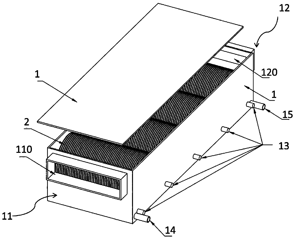
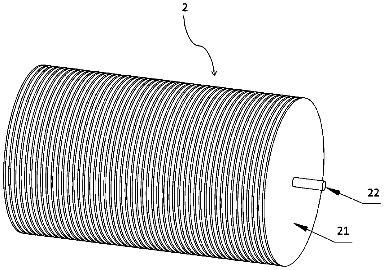
[0038] like figure 1As shown, a pumpless solution dehumidification and regeneration device based on solution immersion in the present invention includes a liquid storage tank 1 containing a dehumidification solution, four dehumidifiers located inside the liquid storage tank 1 and distributed along the direction of gas flow. In the unit 2, a dehumidification solution 4 is contained in the liquid storage tank 1, and the lower end of the dehumidification unit 2 is soaked in the dehumidification solution 4.

[0039] The gas inlet 110 is located in the upper area of ​​the side wall of the first end 11 of the liquid storage tank 1, the gas outlet 120 is located in the upper area of ​​the side wall of the second end 12 of the liquid storage tank 1, and the gas enters the liquid storage tank 1 through the gas inlet 110. The dehumidification of the ga...


PUM


Abstract

The invention discloses a pump-free solution dehumidifying and regenerating device based on solution infiltration. The ump-free solution dehumidifying and regenerating device based on solution infiltration comprises a solution storage tank and a dehumidifying unit which is arranges inside the solution storage tank and is used for removing moisture in gas, wherein the dehumidifying unit comprises aplurality of dehumidifying discs and a rotating shaft (22) penetrating through centers of the dehumidifying discs, the two ends of the rotating shaft penetrate out of the solution storage tank and are fixed on the side wall of the solution storage tank, each dehumidifying disc comprises at least one wetting layer used for infiltrating a dehumidifying solution and a fixing layer which is located on the surface of the wetting layer and is used for fixing the wetting layer. According to the device, solution distribution on the dehumidifying solution is conducted by utilizing the infiltration action of a wetting material, in addition, the solution on a heat and mass transfer surface is updated through rotation of the dehumidifying discs and small-scale flowing of the solution on the wet material, the problem of solution carrying of to-be-treated air is remarkably alleviated, meanwhile, the stability of a wetting surface is improved, and the device has an excellent application prospect inthe case that the installation position of equipment is shaken and vibrated.

Description

technical field [0001] The invention relates to a dehumidification device, in particular to a pumpless solution dehumidification regeneration device based on solution immersion. Background technique [0002] Solution dehumidification and drying is an efficient gas humidity adjustment method. In the dehumidifier, the solution with low water vapor partial pressure is contacted with the gas to be dehumidified, and the water in the gas is driven to transfer to the solution by using the water vapor partial pressure difference to achieve the purpose of reducing the moisture content of the gas; in the regenerator, The solution with high water vapor partial pressure is contacted with the regeneration gas to drive the water in the solution to transfer to the gas to achieve the purpose of increasing the concentration of the solution. This technology can achieve gas dehumidification driven by low-grade heat energy, and has the characteristics of efficient use of waste heat energy. At ...

Claims


Application Information

Patent Timeline
IPC IPC(8): F24F3/14F24F11/89F24F13/30
Inventor 殷勇高王远吕玥张凡
Owner SOUTHEAST UNIV
Features
  • Generate Ideas
  • Intellectual Property
  • Life Sciences
  • Materials
  • Tech Scout
  • Unparalleled Data Quality
  • Higher Quality Content
  • 60% Fewer Hallucinations
Learn More