Supercharge Your Innovation With Domain-Expert AI Agents!

Ultrasonic resonance multi-axis bending fatigue test device

A bending fatigue and experimental device technology, which is applied in the direction of measuring device, vibration test, elastic test, etc., can solve the problems of large error in direct simulation simulation results and lack of multi-axis fatigue test methods, so as to reduce the impact and realize the freedom of fixed connection Fatigue loading in vibration state, effect of preventing fracture

Pending Publication Date: 2019-05-17
SICHUAN UNIV
View PDF0 Cites 0 Cited by
  • Summary
  • Abstract
  • Description
  • Claims
  • Application Information

AI Technical Summary

Problems solved by technology

However, the current research on multiaxial fatigue theory is not as comprehensive and in-depth as the research on uniaxial fatigue theory, especially for ultra-high cycle long-life multiaxial fatigue research.
The main reason is that there is a lack of a multi-axial fatigue testing method suitable for long-life fatigue testing. Therefore, the research methods and devices for material fatigue under the combination of long-life and multi-axial conditions need to be further supplemented and improved.
[0004] In addition, because the structural life of mechanical parts cannot be effectively predicted by analytical theoretical methods, the direct simulation results of existing numerical calculations have large errors. Indirectly obtained, so in order to promote the further development of our country in the field of fatigue, in response to the working conditions of actual engineering materials and components, it has become an inevitable demand to design a test device for high-speed multi-axial fatigue to achieve long-life multi-axial cyclic fatigue testing

Method used


Image

  • Ultrasonic resonance multi-axis bending fatigue test device
  • Ultrasonic resonance multi-axis bending fatigue test device
  • Ultrasonic resonance multi-axis bending fatigue test device

Examples


Embodiment

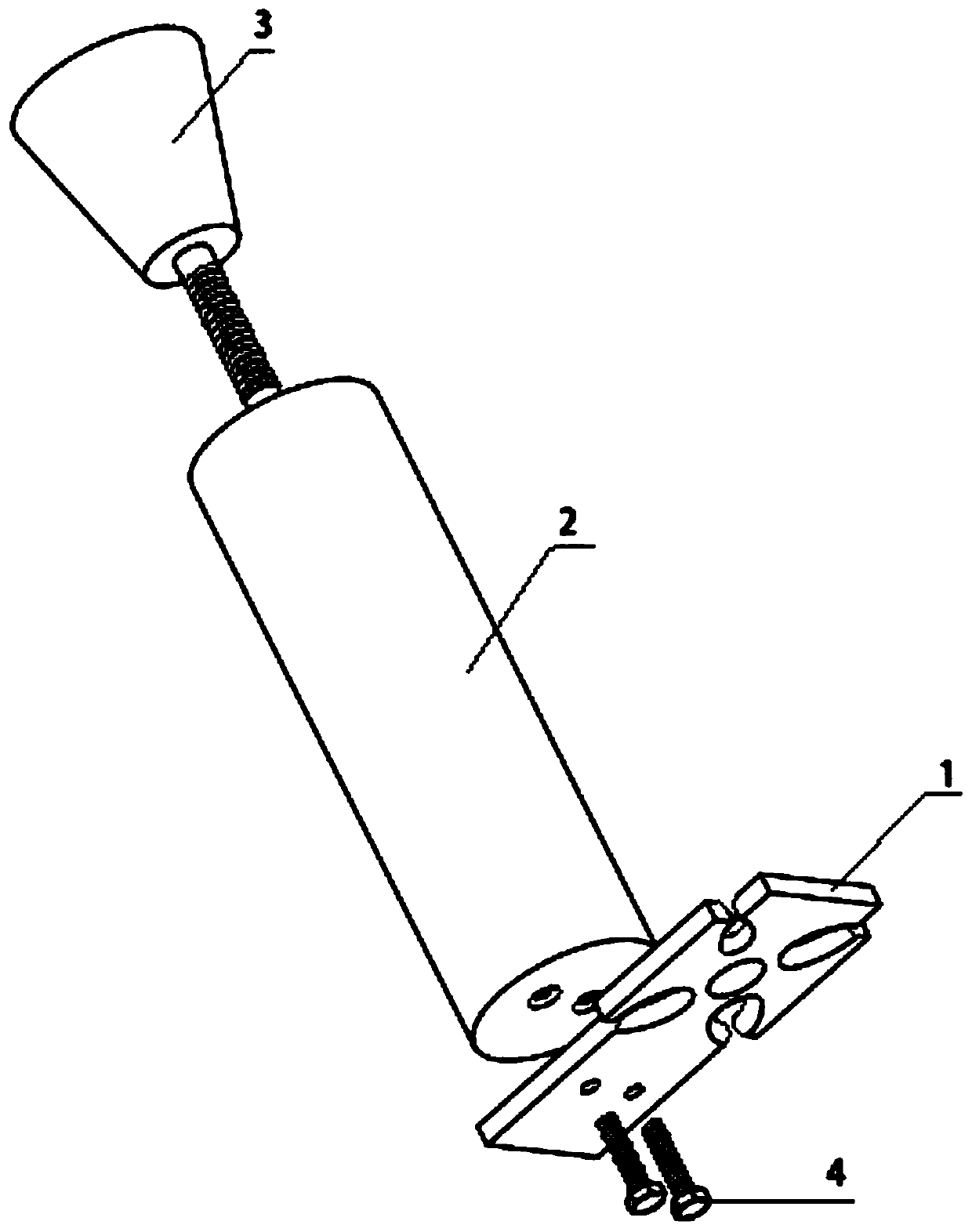
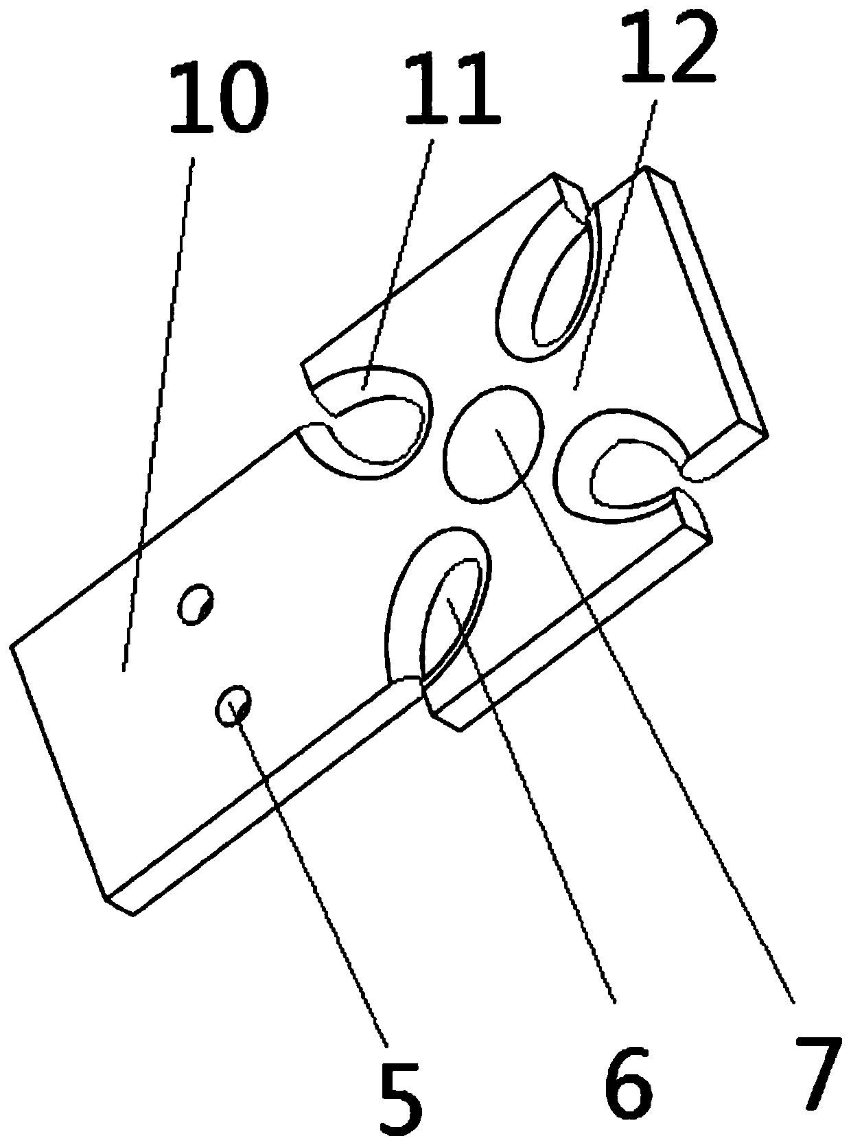
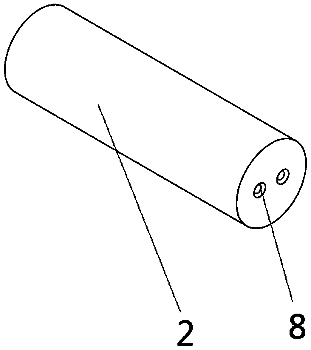
[0028] Such as Figure 1 to Figure 4 As shown, an ultrasonic resonance multiaxial bending fatigue test device of the present invention includes an auxiliary fixing connector 2, and one end of the auxiliary fixing connector 2 is provided with a third connecting hole 9, and the third connecting hole 9 is located at the auxiliary fixing connector. 2, a connecting rod is provided in the third connecting hole 9, and the connecting rod is connected with the third connecting hole 9 through threads, one end of the connecting rod is connected with the third connecting hole 9 through threads, and the other end is provided with The connecting block 3, the connecting block and the connecting rod are integrally structured, the connecting rod 3 can be quickly loaded and unloaded with the auxiliary fixed connector 2 through the provided connecting rod, and the connecting block 3 can be connected with the joint of the fatigue loader to ensure The auxiliary fixing connector 2 can be installed ...


PUM


Abstract

The invention discloses an ultrasonic resonance multi-axis bending fatigue test device. The ultrasonic resonance multi-axis bending fatigue test device comprises an auxiliary fixing connection piece,wherein one end of the auxiliary fixing connection piece is provided with a test piece, the test piece is a crossed structure formed by perpendicularly crossing of long plate and a short plate, four crossed parts of the test piece are all provided with an arc-shaped opening, the long plate of the test piece comprises a loading segment and a test segment, the loading segment is connected with the auxiliary fixing connection piece, and the arc-shaped openings are all located in the test segment. For the ultrasonic resonance multi-axis bending fatigue test device provided by the invention, the test piece for the test is a non-complete symmetrical orthogonal resonance type test piece design, thus, the test can realize transverse vibration of two directions under a cantilever connection form, the test piece generates a fast multi-axis fatigue loading state due to ultrasonic frequency vibration bending in two directions, and a fatigue break generation position of the test piece is guaranteedto be at a crossed central part; the test piece is connected with the auxiliary fixing connection piece through many screw holes, stress concentration of a loading position is reduced, influence of fastening connection on vibration modality is reduced as much as possible, and the test piece is prevented from breaking at the loading segment.

Description

technical field [0001] The invention relates to the technical field of metal material fatigue tests, in particular to an ultrasonic resonance multi-axis bending fatigue test device. Background technique [0002] Fatigue failure is the main failure mode of components or structures under alternating loads. The main failure mode of components and structures such as vehicles, aircraft, gear turbine blades, springs, etc. is fatigue damage. In actual engineering accidents, the proportion of accidents related to fatigue damage accounts for 80%. Therefore, the research on the fatigue properties of materials has always been a subject of research and concern in engineering circles at home and abroad. In aerospace, nuclear industry, machinery and other fields, some structural components need to withstand high-frequency vibration loads during work. Especially when there are other loads present, the resulting composite damage will greatly accelerate the failure of structural component...

Claims


Application Information

Patent Timeline
IPC IPC(8): G01M5/00G01M7/02G01N3/32
Inventor 王宠邓海鳞王清远刘永杰黄志勇范海冬
Owner SICHUAN UNIV
Features
  • R&D
  • Intellectual Property
  • Life Sciences
  • Materials
  • Tech Scout
  • Unparalleled Data Quality
  • Higher Quality Content
  • 60% Fewer Hallucinations
Learn More