
Display system and display device

A technology of display system and display screen, applied in optical elements, optics, instruments, etc., can solve the problems of difficult arrangement and processing of sub-lenses 21, affecting the quality of displayed images, and high cost, so as to increase the processing difficulty and cost, improve the Stereoscopic display effect, the effect of reducing processing difficulty and cost

Active Publication Date: 2019-05-17
BOE TECH GRP CO LTD +1
View PDF38 Cites 6 Cited by
  • Summary
  • Abstract
  • Description
  • Claims
  • Application Information

AI Technical Summary

Problems solved by technology

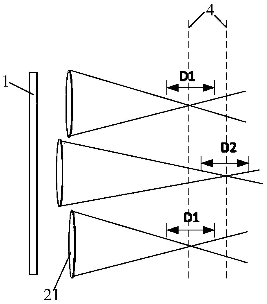
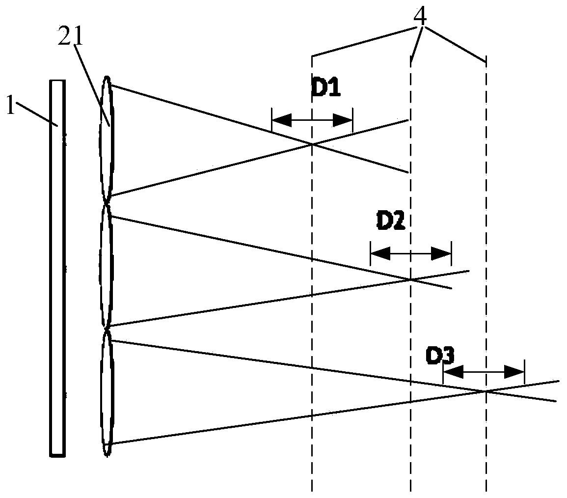
However, the arrangement and processing of sub-lenses 21 with different calibers and focal lengths is difficult and costly
[0006] Existing Technology 3: Rapidly moving the lens array to generate multiple imaging center depth planes, but the rapid movement of the lens array will generate large noise and affect the quality of the displayed image

Method used


Image

  • Display system and display device
  • Display system and display device
  • Display system and display device

Examples


Embodiment Construction

[0036] In order to enable those skilled in the art to better understand the technical solution of the present invention, a display system and a display device provided by the present invention will be further described in detail below with reference to the drawings and specific embodiments.

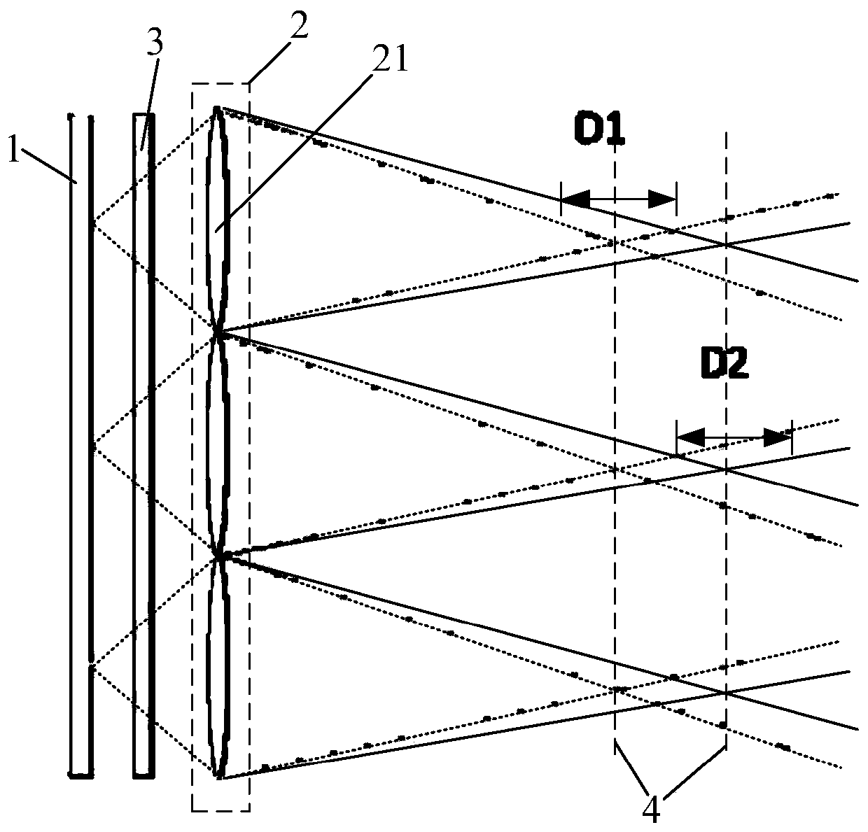
[0037] In order to solve the technical problems of low display image resolution, high implementation difficulty, high cost and impact on display image quality existing in the existing technical solutions for increasing the stereoscopic display depth of field of the display system, Embodiment 1 of the present invention provides a display system ,like image 3 and Figure 4 As shown, it includes a display screen 1 and a lens array 2. The lens array 2 is arranged on the display side of the display screen 1, and is used to convert the two-dimensional image displayed on the display screen 1 into a three-dimensional image. The display system also includes a light modulation structure 3, and the...


PUM


Abstract

The invention provides a display system and a display device. The display system comprises a display screen and a lens array, wherein the lens array is arranged on the display side of the display screen and is used for converting a two-dimensional image displayed by the display screen into a three-dimensional image; the display system further comprises a light modulation structure; and the light modulation structure is fixedly arranged between the display screen and the lens array and is used for modulating the length of an optical path, through which the display light sent by the display screen is irradiated into the lens array into two types. Compared with the existing technology of increasing the stereo display depth of field through dynamically adjusting the positions of sub-lenses inthe lens array, the display system does not reduce the resolution ratio of the three-dimensional image and is capable of avoiding the positions of the sub-lenses from generating noise to influence theimage display; and compared with the existing technology of increasing the stereo display depth of field through setting the sub-lenses in the lens array into different focal lengths and calibers, the display system does not need to carry out different designs on the sub-lenses in the lens array, thereby reducing the processing difficulty and cost of the whole display system.

Description

technical field [0001] The present invention relates to the field of display technology, in particular to a display system and a display device. Background technique [0002] At present, in an integrated imaging display system, a lens array is usually arranged on the display side of the display screen for displaying two-dimensional images to realize three-dimensional image display on the display screen. That is, the lens array can make the image displayed on the display screen present a three-dimensional effect. [0003] The object distance and lens focal length of the integrated imaging display system determine the image distance of the displayed image. The image distance of the displayed image of the display system refers to the distance between the three-dimensional image and the optical center of the lens. The image distance represents the central depth plane of the three-dimensional stereoscopic imaging. Location. The central depth planes of three-dimensional stereosc...

Claims


Application Information

Patent Timeline
Patent Type & Authority Applications(China)
IPC IPC(8): G02B27/22G02B27/26G02B30/25
Inventor 马新利陈东川钱学强刘冰洋王凯旋
Owner BOE TECH GRP CO LTD
Learn More