Supercharge Your Innovation With Domain-Expert AI Agents!

Cohesionless soil repose angle measuring instrument

An angle of repose and measuring instrument technology, applied in the direction of instruments, flow characteristics, measuring devices, etc., can solve the problems of inconvenient operation, low test efficiency, and poor precision, and achieve the effects of convenient processing, convenient operation, and simple structure

Pending Publication Date: 2019-05-21
安徽省引江济淮集团有限公司 +1
View PDF13 Cites 1 Cited by
  • Summary
  • Abstract
  • Description
  • Claims
  • Application Information

AI Technical Summary

Problems solved by technology

[0004] For this reason, the embodiment of the present invention provides a non-cohesive soil angle of repose measuring instrument to solve the problem of low test efficiency and poor accuracy in the prior art due to the relatively simple structure and inconvenient operation of traditional angle of repose measuring instruments. question

Method used


Image

  • Cohesionless soil repose angle measuring instrument
  • Cohesionless soil repose angle measuring instrument
  • Cohesionless soil repose angle measuring instrument

Examples


Embodiment 1

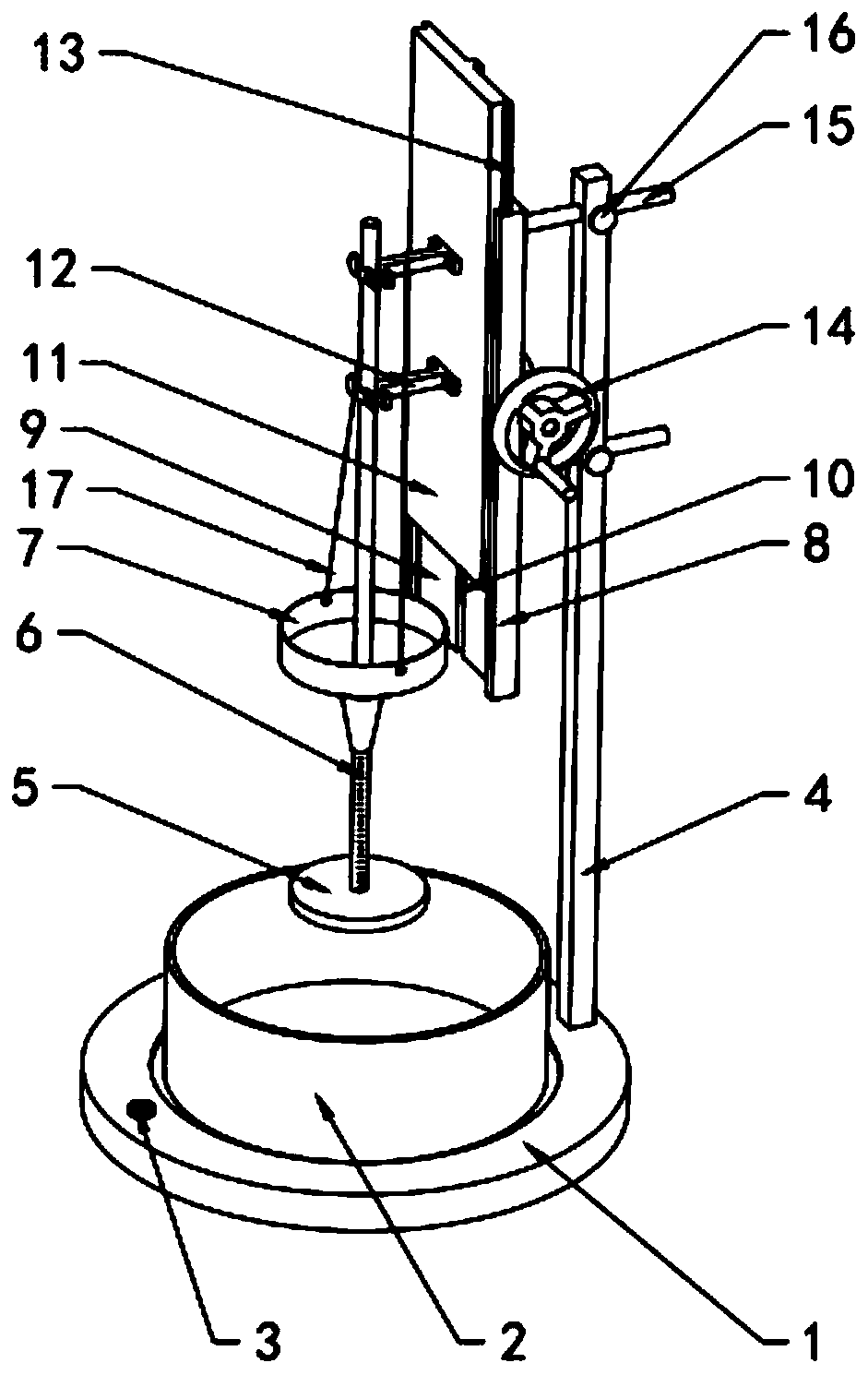
[0027] see Figure 1~3 , the instrument for measuring the angle of repose of cohesive soil includes a base 1, a fixed seat plate 8, a measuring disc 5, a connecting rod 6, a funnel 7 and a lifting mechanism. A vertical support rod 4 is fixed on one side of the base 1, and the The seat plate 8 is fixed on the upper side of the support rod 4, the upper end of the connecting rod 6 is slidably connected to the fixed seat plate 8 through the guide mechanism, the lifting mechanism is arranged on the fixed seat plate 8, the lifting mechanism is connected with the guiding mechanism and drives the connecting rod 6 to lift, The measuring disc 5 is horizontally fixed on the lower end of the connecting rod 6, and a measuring scale is arranged on the connecting rod 6. The funnel 7 is sleeved on the connecting rod 6. The inner diameter of the lower end of the funnel 7 is larger than the diameter of the connecting rod 6, so that the inner diameter of the funnel 7 can be ensured. The sand smo...

Embodiment 2

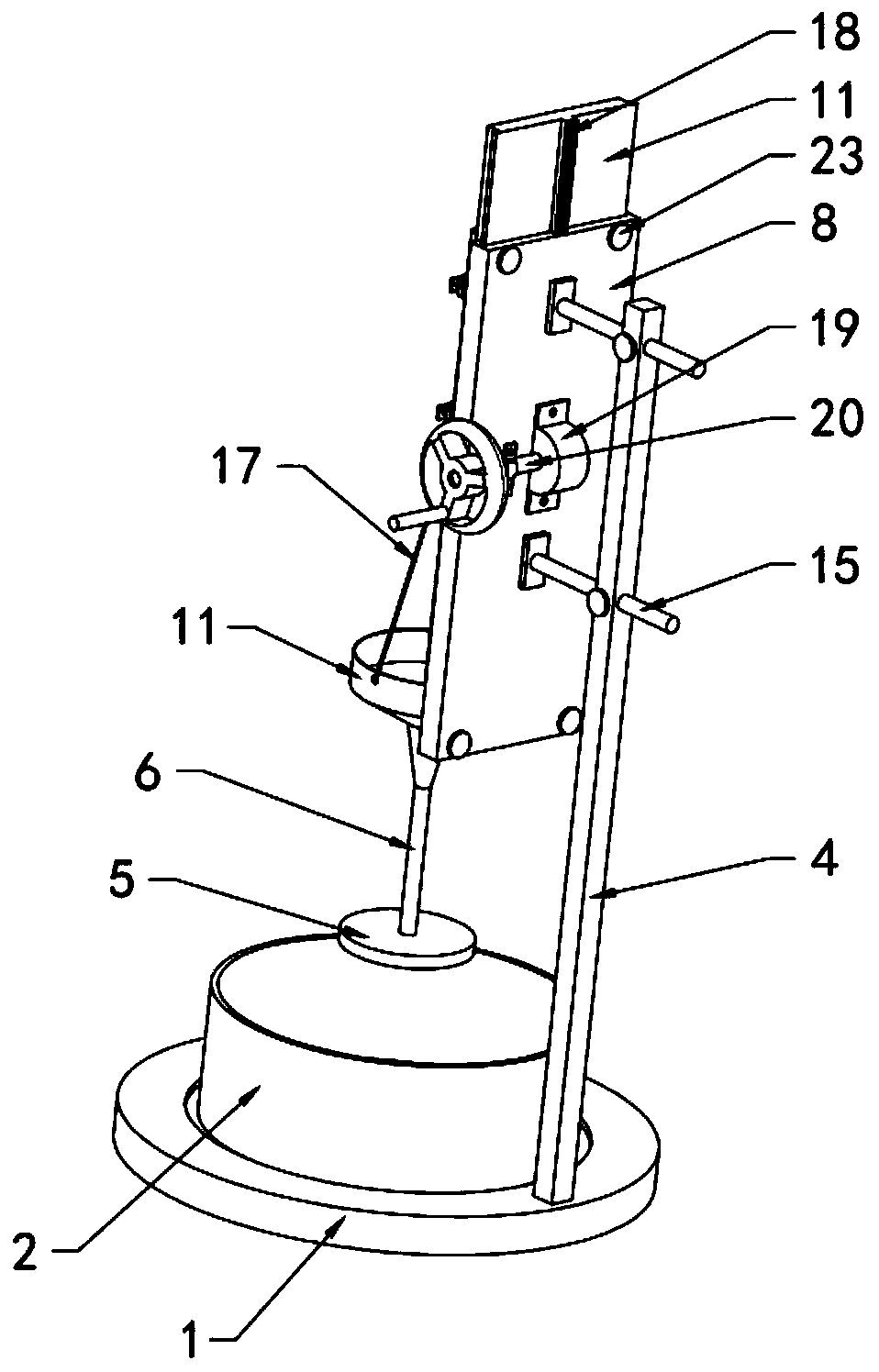
[0038] see Figure 4 , the connecting rod 6 in this embodiment includes a first connecting rod 601 and a second connecting rod 602, the first connecting rod 601 is fixed on one side of the guide plate 11, and the upper end of the second connecting rod 602 is magnetically connected to the lower end of the first connecting rod 601. The suction is fixed, and the measuring disc 5 is fixed on the lower end of the second connecting rod 602 . In this embodiment, the connecting rod 6 is designed in two sections, so that the funnel 7 can be placed and removed very conveniently. It is necessary to disassemble the first connecting rod 601, directly disconnect the second connecting rod 602 from the first connecting rod 601, and then put the funnel 7 on the second connecting rod 602. When the sand sample on the measuring disc 5 is covered, By disconnecting the connecting rod, the funnel 7 is taken off for underwater measurement. The operation is very convenient, and the measurement effic...


PUM

PropertyMeasurementUnit
diameteraaaaaaaaaa

Abstract

The invention discloses a cohesionless soil repose angle measuring instrument and relates to the geotechnical testing equipment technology field. The measuring instrument comprises a pedestal, a fixedseat plate, a measuring disc, a connecting rod, a funnel and a lifting mechanism. One side of the pedestal is fixed with a vertical support rod. The fixed seat plate is fixed on one side of the upperportion of a support rod. The upper end of the connecting rod is slidably connected to the fixed seat plate through a guiding mechanism. The lifting mechanism is arranged on the fixed seat plate. Thelifting mechanism is connected with the guiding mechanism and drives the connecting rod to lift. The measuring disc is horizontally fixed at the lower end of the connecting rod, and measuring scalesare arranged on the connecting rod. The funnel sleeves the connecting rod. The lifting mechanism drives the measuring disc to be accurately and quickly lifted and lowered through the guiding mechanism, the structure is simple, operation and processing are convenient and cost is low. After new equipment is used, 30 to 50 groups of tests or even more can be performed for each day, and work efficiency and measurement accuracy are greatly improved.

Description

technical field [0001] The embodiments of the present invention relate to the technical field of geotechnical testing equipment, and in particular to a measuring instrument for the angle of repose of cohesive soil. Background technique [0002] The angle of repose test of cohesionless soil is to measure the angle of repose of cohesionless soil in air-dried state and underwater state, and it is suitable for pure sandy soil without clay and silt. The angle of repose is the maximum slope angle formed by the natural slope and the horizontal plane when the cohesionless soil is accumulated in a loose state. [0003] In the current angle of repose test of geotechnical tests, the traditional angle of repose measuring instrument has a relatively simple structure and is inconvenient to operate. The test sand sample will be accidentally knocked over, which will seriously affect the test results. The test rework rate is extremely high, which affects work efficiency. Using the original ...

Claims


Application Information

Patent Timeline
Patent Type & Authority Applications(China)
IPC IPC(8): G01N11/00
Inventor 王卉徐迎春程陈江永强耿宏斌王同如金习武吕强胡睿崔彪孙荪朱斌林叶英汪然宋在玖
Owner 安徽省引江济淮集团有限公司
Features
  • R&D
  • Intellectual Property
  • Life Sciences
  • Materials
  • Tech Scout
  • Unparalleled Data Quality
  • Higher Quality Content
  • 60% Fewer Hallucinations
Learn More