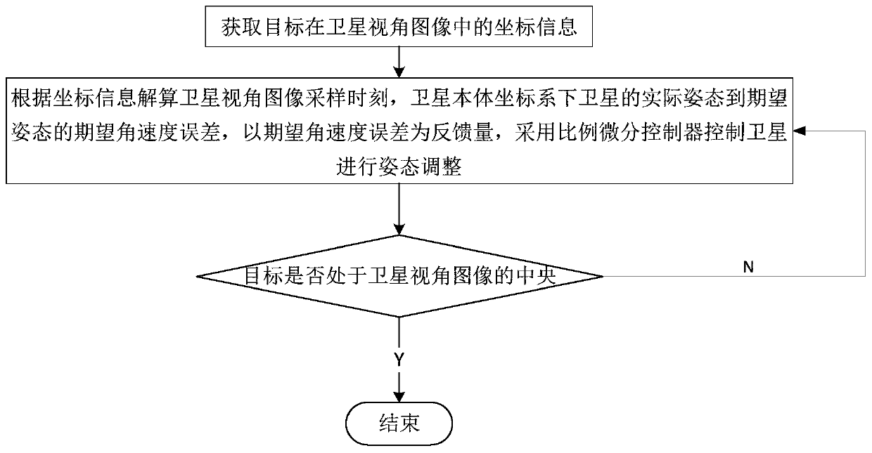
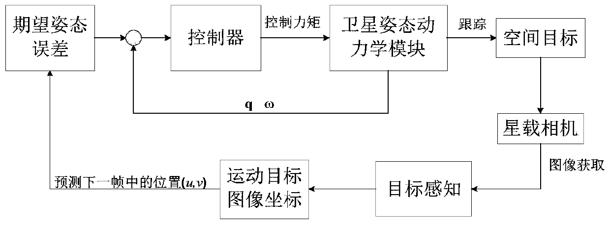
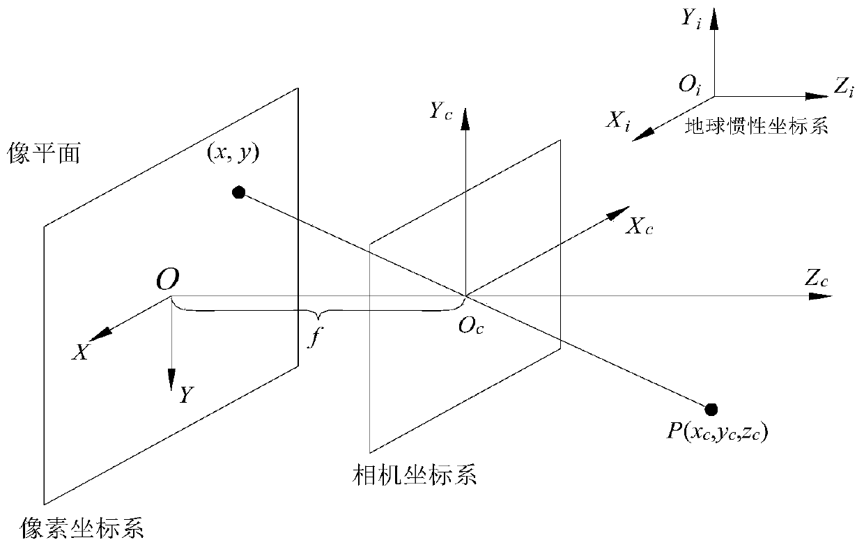
Video satellite moving target tracking imaging method and device based on image guidance
A technology for tracking imaging and moving targets, which is applied in image analysis, image data processing, and control of finding targets, etc. It can solve the problems that position and speed information cannot be known in advance, calculation of expected attitude, and difficult to achieve autonomous gaze tracking imaging of targets. Achieve the effect of improving image processing accuracy, simple and fast algorithm, and easy engineering realization
- Summary
- Abstract
- Description
- Claims
- Application Information
AI Technical Summary
Problems solved by technology
Method used
Image
Examples
Embodiment 1
[0137] The optimization of embodiment 1PD controller parameter
[0138] (1) Optimization of the minimum maneuvering time objective, optimizing the parameters of the PD controller to make the adjustment time of the system as short as possible. Assuming that the target is at (1700, 1400) in the pixel coordinate system at the initial moment, the target function adjustment time T is defined as the time required to control the deviation angle α between the target line of sight and the visual axis to within 0.25°.
[0139] Use genetic algorithm to optimize to obtain the shortest adjustment time, set the population size to 20, crossover probability to 0.8, K p and K d The value ranges of are [1,20] and [1,60] respectively.
[0140] The optimized result obtained is:
[0141]
[0142] Using the optimization results obtained in (25) to simulate the tracking imaging process, the results are as follows Figure 5 As shown, the three curves corresponding to the error Euler angles of ...
Embodiment 2
[0148] The space target video captured by the Tiantuo-2 video satellite in orbit is used as the image input of the control loop, the video image is 25 frames per second, and the resolution is 960×576. The control part is implemented through simulation, and the image changes caused by attitude adjustment are simulated. The image is cropped and scaled to 2300×1700, embedded in the frame with actual size of 3500×2900, and filled with white.
[0149] Figure 7 It shows the process of staring and tracking a space moving target. The outer black frame in the figure represents the satellite field of view, the square frame represents the perceived target, the star mark represents the satellite boresight, that is, the center of the image plane, and the luminous bright spot in the figure is the target. Initially, the target is not in the center of the image plane. Through the control method provided by this application, the target is imaged in the center of the screen, effectively reali...
Embodiment 3
[0155] The city video taken by SkySat video satellite in orbit is used as the image input of the control loop. The video image is 29 frames per second and the resolution is 1104×622. The control part is realized through simulation, and the image changes caused by attitude adjustment are simulated.
[0156] In this embodiment, the video satellite is staring at the ground at the initial moment, and the attitude angle and angular velocity at the initial moment are [0.1, -50, 15] deg and [-0.1, 0.4, 0] deg / s respectively. After cropping, the image is scaled to 2900×1800, which is the same as in the second embodiment, embedded in a picture with an actual size of 3500×2900, and filled with white. Figure 9 (a) to (f) show the process of gazing and tracking the aircraft target. The peripheral black frame in the figure represents the satellite field of view, and the small frame in the picture area represents the perceived target (obtained according to the methods disclosed in CN2015105...
PUM
 Abstract
Description
Claims
Application Information
 - R&D
- Intellectual Property
- Life Sciences
- Materials
- Tech Scout
- Unparalleled Data Quality
- Higher Quality Content
- 60% Fewer Hallucinations
Browse by: Latest US Patents, China's latest patents, Technical Efficacy Thesaurus, Application Domain, Technology Topic, Popular Technical Reports.
© 2025 PatSnap. All rights reserved.Legal|Privacy policy|Modern Slavery Act Transparency Statement|Sitemap|About US| Contact US: help@patsnap.com


