
Magnetic component and manufacturing method thereof

A technology of magnetic components and magnetic components, applied in the direction of preventing/reducing unwanted electric/magnetic effects, transformer/inductor casing, transformer/inductor coil/winding/connection, etc. The molded shell cannot shield the magnetic field, high magnetic permeability and other problems, so as to achieve the effect of high current and suitable for batch automatic production

Pending Publication Date: 2019-05-21
MOSHANG ELECTRONICS TECH SHANGHAI CO LTD
View PDF4 Cites 0 Cited by
  • Summary
  • Abstract
  • Description
  • Claims
  • Application Information

AI Technical Summary

Problems solved by technology

The preformed shell provides a container for ferromagnetic colloid, which can be realized by plastic injection molding, ceramic co-firing, photolithography and development, etc., which is helpful to realize the simple structure of the component, but the preformed shell cannot shield the magnetic field, nor help for high current
[0004] Prior art 2, the Chinese invention patent "Manufacturing method of coil-embedded inductor using soft magnetic molding liquid and coil-embedded inductor manufactured by the above-mentioned manufacturing method" (application publication number: CN107683515A) proposes a A coil-embedded inductor manufacturing method, the soft magnetic powder is mixed with an organic carrier and then injected into the shell with a coil to solidify. This scheme is simple to implement, but because only the mixed molding liquid forms a magnetic circuit, the High magnetic permeability is required, which will lead to the maximum required particle size of 50 μm to 150 μm, and the eddy current loss is too large. In addition, the solid content of the soft magnetic powder in the molding liquid is too high to flow, resulting in bubbles or gaps in the package.

Method used


Image

  • Magnetic component and manufacturing method thereof
  • Magnetic component and manufacturing method thereof
  • Magnetic component and manufacturing method thereof

Examples


Embodiment 1

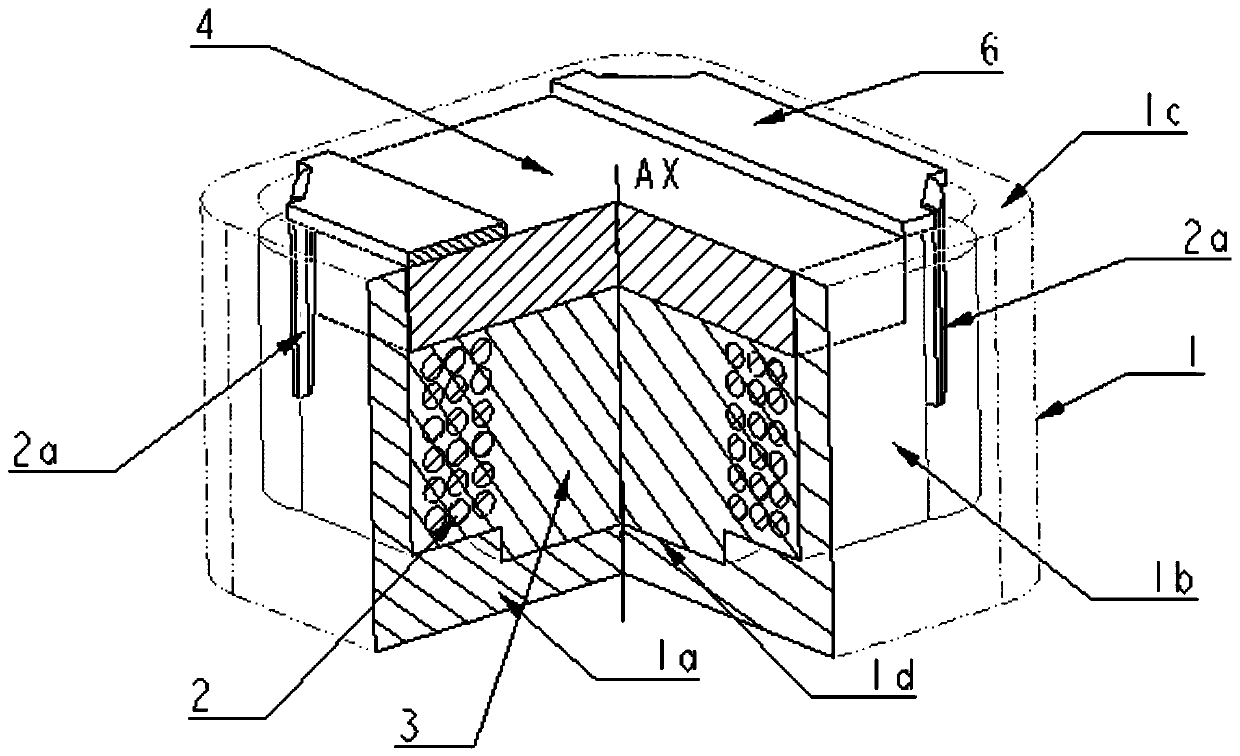
[0060] The surface mount magnetic component involved in this embodiment has an external dimension of 12mm×12mm×8.5mm, which belongs to the category of power inductors. Such as figure 1 Shown is a perspective cutaway view of this surface mount power inductor. It includes a soft magnetic shell 1 made of manganese zinc ferrite, the soft magnetic shell has a bottom plate 1a, a side wall 1b formed along the edge of the bottom plate and extending vertically toward the bottom plate, and an opening 1c opposite to the bottom plate, and in An accommodation space is provided in the housing; an air-core coil 2 is placed in the accommodation space; the air-core coil 2 has a winding helical axis AX, and the air-core coil 2 is placed perpendicular to the direction of the bottom plate 1a of the soft ferrite housing according to the helical axis AX. The inner wall surface of the magnetic housing 1 perpendicular to the screw axis AX (in this embodiment, the inner side of the bottom plate 1a) i...

Embodiment 2

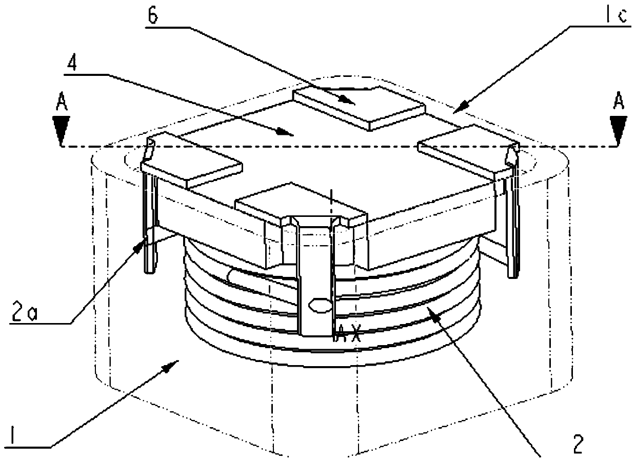
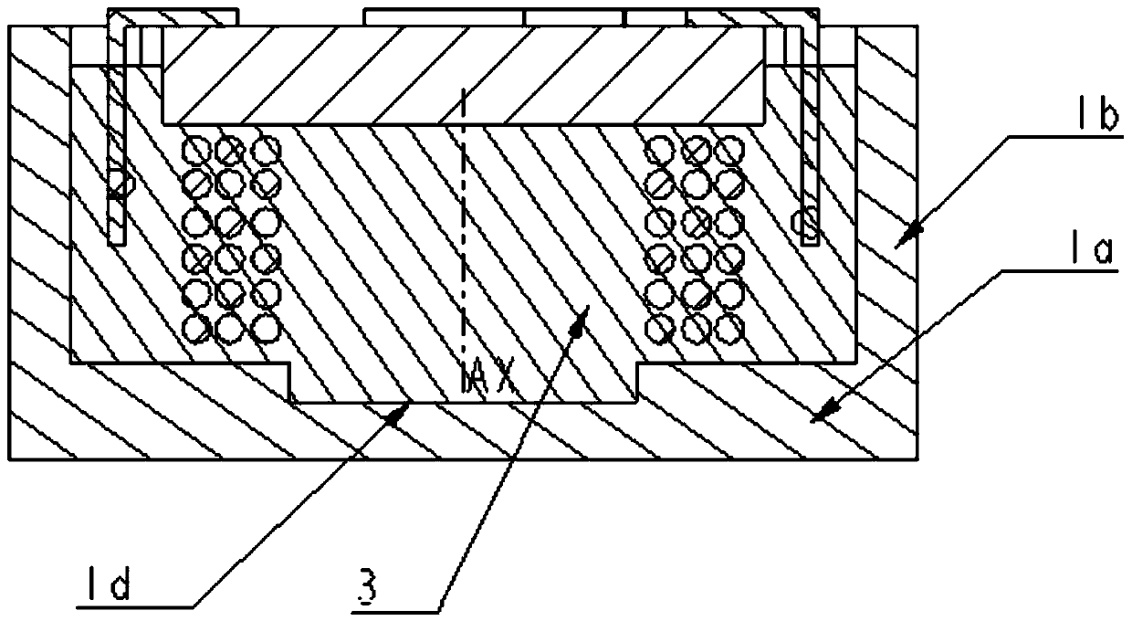
[0063] This embodiment relates to a surface-mounted magnetic component, which has double windings and can be used as a coupling inductor, a common-mode inductor, an isolation transformer, etc., and its external dimensions are 12mm×12mm×8.5mm. Figure 2(a) is a perspective view of the magnetic element, and Figure 2(b) is a cross-sectional view along AA'. It includes a soft magnetic shell 1 made of nickel-zinc ferrite with a magnetic permeability of 400; the soft magnetic shell has a bottom plate 1a, a side wall 1b formed along the edge of the bottom plate and extending vertically toward the bottom plate, And the opening 1c opposite to the bottom plate, and provide an accommodation space in the casing; two air-core coils 2 are placed in the accommodation space; the air-core coil 2 has a winding helical axis AX, and the air-core coil 2 is perpendicular to the soft coil according to the helical axis AX The ferrite shell is placed in the direction of the bottom plate 1a, and a reces...

Embodiment 3

[0065] This embodiment relates to a plug-in magnetic component and its manufacturing method, which can be used as a PFC inductor, reactor, etc., and is widely used in the fields of industrial power supply and vehicle electronic control. Such as image 3 As shown, from left to right and from top to bottom is the manufacturing process of the plug-in magnetic component. First, a soft magnetic shell 1 is provided, made of manganese zinc ferrite, the magnetic permeability of the manganese zinc ferrite material is greater than 2000, and the saturation magnetic flux density at room temperature is greater than 0.5T; the soft magnetic shell has a bottom plate 1a, along the edge of the bottom plate Form and extend the side wall 1b perpendicular to the bottom plate, and the opening 1c opposite to the bottom plate, and provide an accommodation space in the casing; an air-core coil 2 is placed in the accommodation space, and the air-core coil is vertically wound with a flat copper wire Ma...


PUM

PropertyMeasurementUnit
Saturation flux densityaaaaaaaaaa
Thermal conductivityaaaaaaaaaa

Abstract

The invention relates to a magnetic component. The magnetic component comprises a soft magnetic shell, a coil and a mixture; the soft magnetic shell is a hollow structure; the coil is arranged in thesoft magnetic shell; the end part of the coil extends out from the soft magnetic shell or is connected with an external terminal; the mixture is filled in the shell; and the coil is immersed in the mixture. Compared with the prior art, the magnetic component in the invention has the advantages: due to the design of a hybrid magnetic circuit composed of the soft magnetic shell and the mixture composed of magnetic powder and resin, the magnetic conductivity of the mixture can be controlled in a reasonable range easy for production; simultaneously, the space utilization rate of the magnetic component is nearly up to 100%; high current is easily realized; therefore, a magnetic shielding high-current magnetic component easy for automatic production is realized; the saturation current thereof isfar higher than that of a general ferrite assembly magnetic component, and is equal to that of an integrally formed magnetic component; but, the reliability is far better than the latter; and furthermore, the magnetic component is more suitable for batch automatic production.

Description

technical field [0001] The present invention relates to a magnetic element and a manufacturing method, in particular to a high-reliability, high-current magnetic shielding element and a manufacturing method thereof. The application fields are magnetic elements such as power inductors, coupled inductors, common-mode inductors, transformers, and reactors. . Background technique [0002] At present, there are two main methods of magnetic component products for industrial applications: one uses the traditional ferrite assembly method, which has a wide range of inductance values, but the disadvantage is that the current it bears is generally small, and it is difficult to fully automate the process; the other is The first type is an integrally formed magnetic component that has achieved great market success in civilian consumer electronics in the past ten years. It is made of a mixture of alloy iron powder and resin with a higher saturation magnetic flux density and a coil that is...

Claims


Application Information

Patent Timeline
IPC IPC(8): H01F27/36H01F27/28H01F27/02
Inventor 黄智褚江端悦涛
Owner MOSHANG ELECTRONICS TECH SHANGHAI CO LTD
Learn More