A cutting insert and a milling tool

A technology of cutting inserts and milling tools, applied in the direction of milling cutting inserts, milling cutters, manufacturing tools, etc., can solve the problem of not optimal cutting performance, and achieve the effect of improved cutting performance, easy manufacturing, and easy grinding

Inactive Publication Date: 2019-05-21
PRAMET TOOLS
View PDF7 Cites 0 Cited by
  • Summary
  • Abstract
  • Description
  • Claims
  • Application Information

AI Technical Summary

Problems solved by technology

[0004] A problem associated with cutting inserts according to EP1157768 is that the cutting performance at small and medium depths of cut is not optimal due to the shape of the cutting edge

Method used


Image

  • A cutting insert and a milling tool
  • A cutting insert and a milling tool
  • A cutting insert and a milling tool

Examples


Embodiment Construction

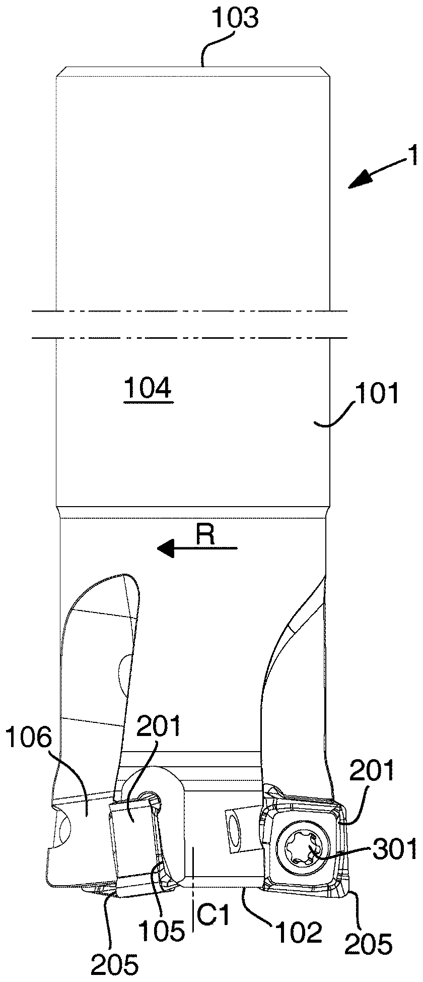
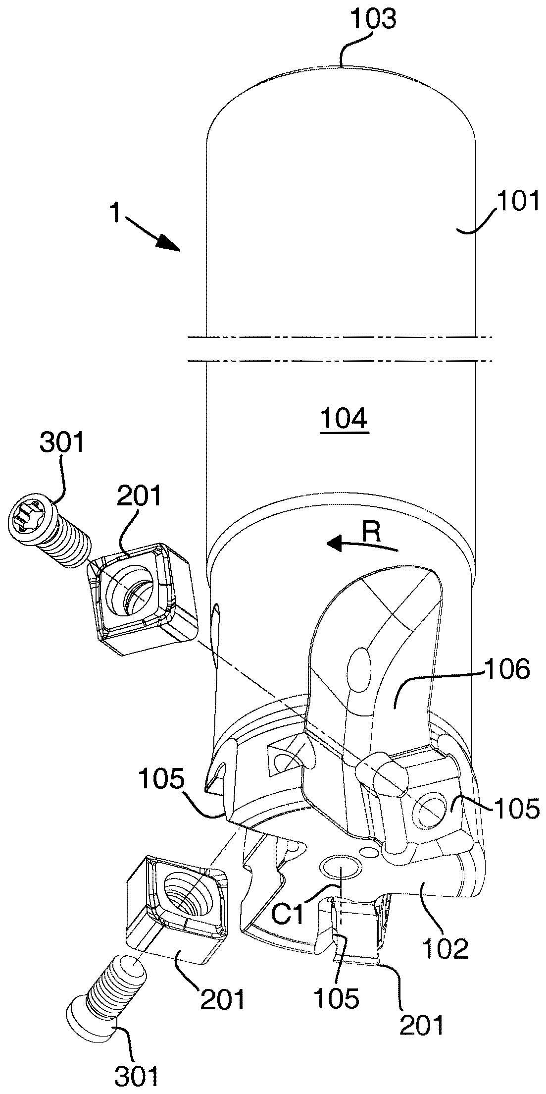
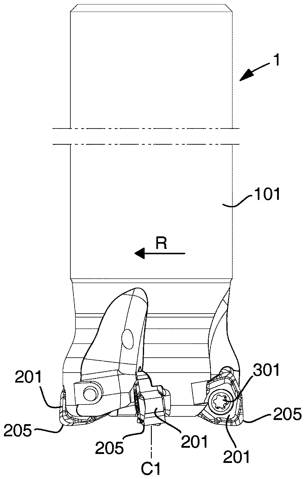
[0054] exist Figure 1-2 A milling tool 1 according to an embodiment of the invention is shown in . The milling tool 1 is rotatable in a direction of rotation R about a central axis of rotation C1. The tool body 101 of the milling tool 1 comprises a front end 102 and a rear end 103 between which an envelope surface 104 extends. At the rear end 103 the milling tool 1 is configured for engagement with a spindle of a machine tool (not shown) and three insert seats 105 are formed in the transition between the front end 102 and the envelope surface 104 . In front of each insert seat 105, as seen in the rotational direction of the tool, a chip flute 106 is provided. Double-sided negative cutting inserts 201 are detachably mounted in each insert seat 106 by means of screws 301 . The cutting insert 201 is mounted at a negative axial setting angle, ie inclined with respect to the axial direction defined by the central axis of rotation, in order to provide axial clearance for double-...


PUM


Abstract

An indexable cutting insert (201) for a milling tool, comprising: an upper side (202); a lower side (203); a side surface (204) connecting the upper and lower sides; at least two identical upper cutting edges (205), each comprising a chip removing major cutting edge (210) and a minor cutting edge (211) extending on opposite sides of a corner edge (209), a major wiper edge (212) extending between the corner edge and the major cutting edge, and a minor wiper edge (213) extending between the corner edge and the minor cutting edge, wherein, as seen in a top view, the major cutting edge and the major wiper edge form an obtuse inner angle of less than 180D and, as seen in a side view, the major wiper edge slopes downward from the corner edge toward the major cutting edge, and the major cutting edge has a first portion (219) sloping downward from the major wiper edge and a second portion (220) which extends in parallel with the upper side.

Description

technical field [0001] The invention relates to a cutting insert according to the preamble of claim 1 . In particular, the present invention relates to a cutting insert configured for chip removal machining of metal workpieces by milling. The invention also relates to a milling tool according to the preamble of claim 16 . The cutting insert and the milling tool according to the invention are particularly suitable for, but not limited to, contouring or profiling milling, ie milling in which surface contours are machined in a workpiece. More precisely, the cutting insert and the milling tool are thus advantageously used for smoothing work, wherein a high surface finish on the machined surface is achieved by means of a wiping edge included on the cutting edge of the cutting insert. The cutting inserts and milling tools can also be used for shoulder milling, ramping, mold / model machining, helical interpolation and plunge milling. [0002] A wiping edge here refers to a cutting ...

Claims


Application Information

Patent Timeline
Patent Type & Authority Applications(China)
IPC IPC(8): B23C5/16
CPCB23C2200/208B23C2200/201B23C2200/0438B23C2200/082B23C2200/0411B23C5/109B23C5/202B23C2200/326
Inventor 扬·比特纳扬·弗尔切克
Owner PRAMET TOOLS
Why Eureka
Try Eureka