Tool turret device applied to machine tool with Y axis

A Y-axis and turret technology, which is applied in the field of machine tools, can solve problems such as impracticability, and achieve the effects of centering adjustment, widening the processing range, and convenient centering adjustment

Active Publication Date: 2019-05-24
津上精密机床(浙江)有限公司
View PDF8 Cites 2 Cited by
  • Summary
  • Abstract
  • Description
  • Claims
  • Application Information

AI Technical Summary

Problems solved by technology

[0003] CNC machine tools generally include a main shaft, a turret and a secondary shaft. For example, the patent publication No. CN208289016U discloses a machine tool turret installation mechanism that is inclined. Realize the movement and then complete the feeding and retracting of the tool, and because the turret can only move in one direction on the inclined pallet, it can only complete the machining action of drilling each time, and if you want to mill the workpiece, can not be achieved

Method used


Image

  • Tool turret device applied to machine tool with Y axis
  • Tool turret device applied to machine tool with Y axis
  • Tool turret device applied to machine tool with Y axis

Examples


Embodiment 1

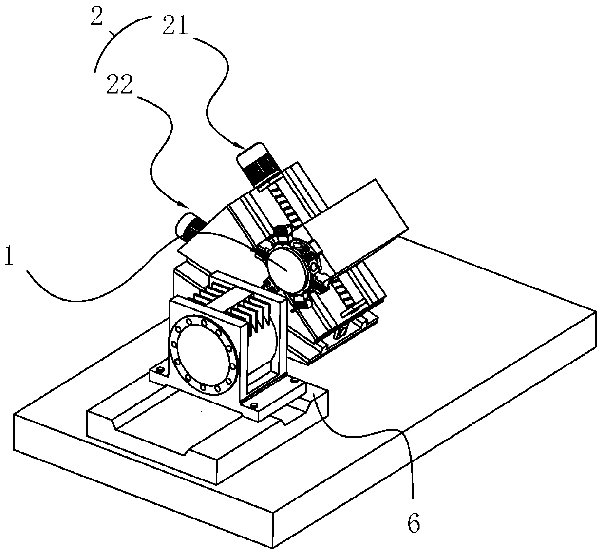
[0035] A kind of turret device applied to a machine tool with Y axis, refer to figure 1 As shown, it includes a turret 1 and a drive mechanism 2. The drive mechanism 2 includes an X-axis drive assembly 21 and a Y-axis drive assembly 22. The Y-axis drive assembly 22 drives the X-axis drive assembly 21 to move, and the X-axis drive assembly 21 Drive the turret 1 to move, and under the action of the Y-axis drive assembly 22, the moving direction of the X-axis drive assembly 21 forms an angle of 15° with the spindle installation reference plane 6. Under the action of the X-axis drive assembly 22, the movement direction of the turret 1 The direction of movement is 30° to the spindle installation datum plane 6 .

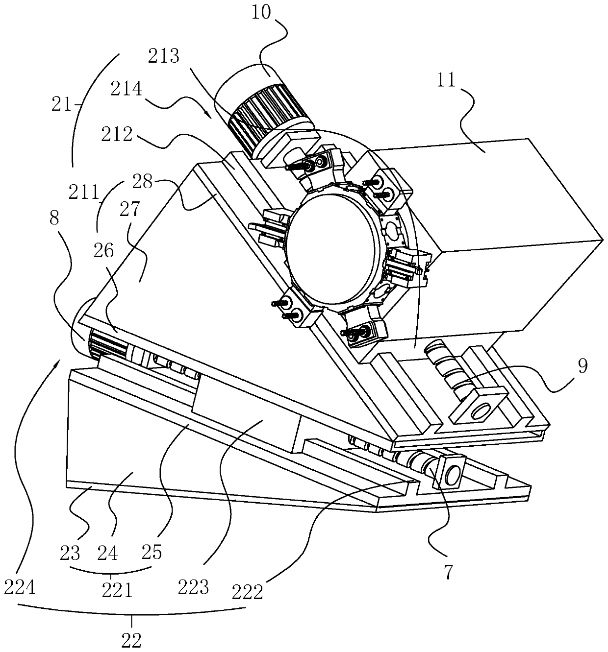
[0036] refer to figure 2 As shown, the Y-axis drive assembly 22 includes a Y-axis slant support plate 221 fixedly installed on the machine bed. The Y-axis slant support plate 221 includes a Y-axis base plate 23 fixed on the machine bed. The reference plane 6 is parallel...

Embodiment 2

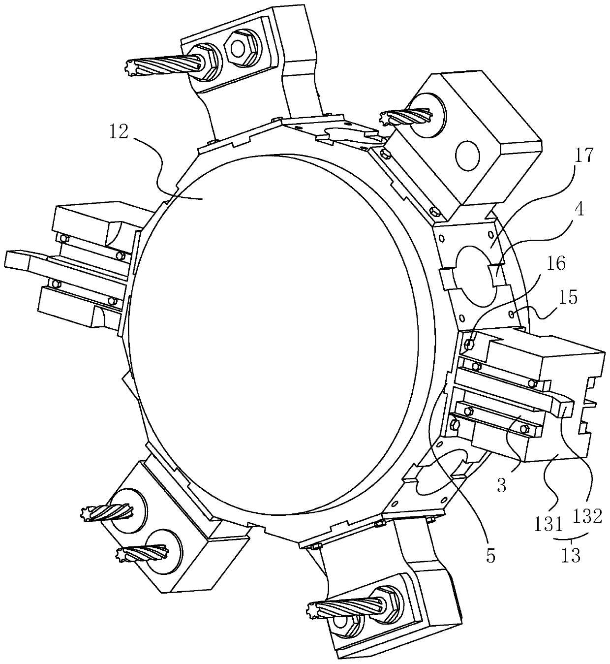
[0042] A turret device applied to a machine tool with a Y axis, the difference from Embodiment 1 is that, refer to Figure 4 As shown, the installation position 3 is at least two installation holes opened along the central axis of the cutter head 12 on the side wall of the fixed knife seat 131 parallel to the end face of the cutter head 12, and a cutter head 132 can be inserted into the installation holes. , The cutter head 132 is a drill bit or a milling cutter, and is locked by a locking bolt.

Embodiment 3

[0044] A turret device applied to a machine tool with a Y axis, the difference from Embodiment 1 is that, refer to Figure 5 As shown, on the mounting surface 17 of the cutter head 12, there are fixed holes 18 arranged radially along the cutter head 12, and a power tool 14 can be installed in the fixed hole 18. The power tool 14 is a power head, and the power head can be selected to have at least Two-axis drilling / milling driven tool holder.


PUM


Abstract

The invention discloses a tool turret device applied to a machine tool with a Y axis. The tool turret device applied to the machine tool with the Y axis comprises a tool turret and a driving mechanism. The driving mechanism comprises an X axis driving assembly and a Y axis driving assembly. The Y axis driving assembly drives the X axis driving assembly to move and the moving direction and a spindle installation datum panel form a first acute angle, and the X axis driving assembly drives the tool turret to move and the moving direction and the moving direction of the X axis driving assembly form a second acute angle. The tool turret device applied to the machine tool with the Y axis can realize the machining of a workpiece milling plane.

Description

technical field [0001] The invention relates to the field of machine tools, in particular to a turret device applied to a machine tool with a Y axis. Background technique [0002] Numerical control machine tool is the abbreviation of digital control machine tool, which is an automatic machine tool equipped with a program control system, which can logically process programs with control codes or other symbolic instructions, and decode them, using coded numbers It means that the numerical control device is input through the information carrier, and various control signals are sent by the numerical control device after calculation and processing to control the movement of the machine tool, and the parts are automatically processed according to the shape and size required by the drawing. [0003] CNC machine tools generally include a main shaft, a turret and a secondary shaft. For example, the patent publication No. CN208289016U discloses a machine tool turret installation mecha...

Claims


Application Information

Patent Timeline
Patent Type & Authority Applications(China)
IPC IPC(8): B23Q39/00B23Q5/40B23Q5/36
Inventor 唐东雷
Owner 津上精密机床(浙江)有限公司
Why Eureka
Try Eureka