Textile printing and dyeing device

A technology of textile printing and dyeing and printing and dyeing boxes, which is applied in the field of textile processing, can solve the problems that fabric rolls of different sizes cannot be fixed and unfolded, and achieve the effect of improving the flatness

Inactive Publication Date: 2019-05-24
高炆圣
View PDF12 Cites 11 Cited by
  • Summary
  • Abstract
  • Description
  • Claims
  • Application Information

AI Technical Summary

Problems solved by technology

[0004] The purpose of the present invention is to provide a textile printing and dyeing device, which can effectively solve the problem that the printing and dyeing device in the prior art cannot fix and unfold the...

Method used


Image

  • Textile printing and dyeing device
  • Textile printing and dyeing device
  • Textile printing and dyeing device

Examples


specific Embodiment approach 1

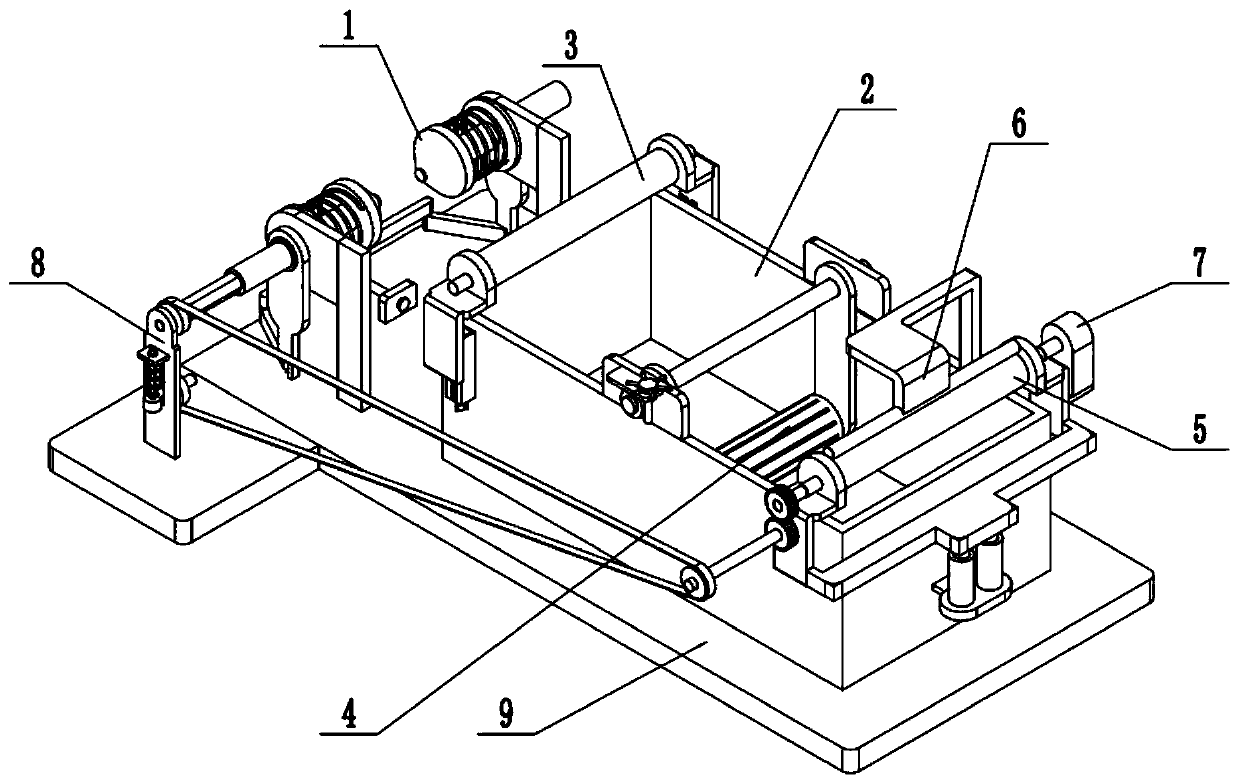
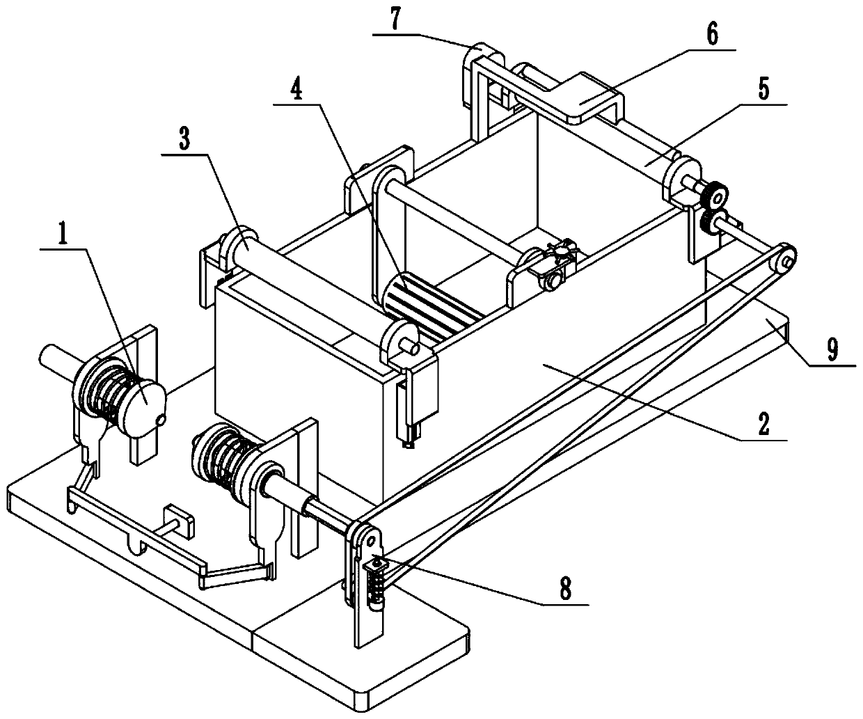
[0032] Such as Figure 1-13 As shown, a textile printing and dyeing device includes a cloth roll clamping mechanism 1, a printing and dyeing box 2 with a hollow top surface, a cloth feeding guide roller mechanism 3, a printing and dyeing guiding roller mechanism 4, a cloth outlet guiding roller mechanism 5, and an auxiliary cloth pressing mechanism 6 , a drive mechanism 7, a linkage mechanism 8 and a base plate 9, the cloth roll clamping mechanism 1 is fixedly connected to the left end of the base plate 9 top surface; the printing and dyeing box 2 is fixedly connected to the middle end of the base plate 9 top surface; The cloth feeding guide roller mechanism 3 is fixedly connected to the upper end on the left side of the printing and dyeing box 2; the printing and dyeing guiding roller mechanism 4 is fixedly connected to the upper end in the middle of the printing and dyeing box 2; Fixedly connected to the upper end of the right side of the printing and dyeing box 2, the auxil...

specific Embodiment approach 2

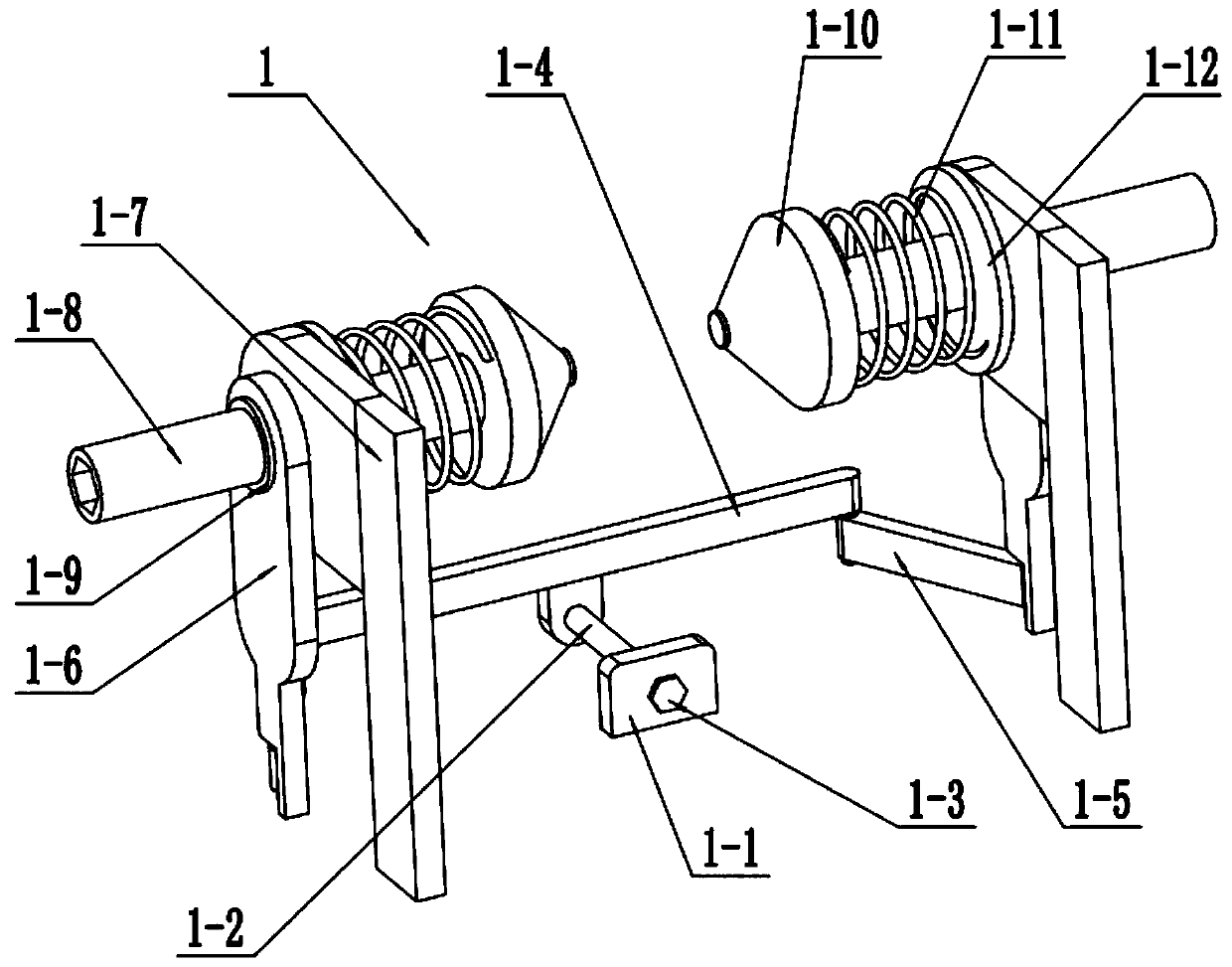
[0033] Such as Figure 1-13 As shown, the cloth roll clamping mechanism 1 includes a fixed seat plate 1-1, a guide shaft 1-2, a limit block 1-3, a push-pull plate 1-4, a push-pull connecting rod 1-5, a movable frame plate 1- 6. Fixed frame plate 1-7, movable shaft 1-8, limit ring 1-9, tapered top tight head 1-10 without cone tip, compression spring 1-11 and spring plate 1-12; The seat plate 1-1 is fixedly connected to the left end of the top surface of the base plate 9; the left and right ends of the guide shaft 1-2 are respectively fixedly connected to the push-pull plate 1-4 and the limit block 1-3, and the center of the guide shaft 1-2 The ends are slidingly fitted and connected to the fixed seat plate 1-1; the front and rear ends of the push-pull plate 1-4 are respectively connected to the left end of a push-pull connecting rod 1-5 through hinge shafts, and the right ends of two push-pull connecting rods 1-5. They are respectively connected to a movable frame plate 1-6 th...

specific Embodiment approach 3

[0034] Such as Figure 1-13 As shown, the cloth feeding guide roller mechanism 3 includes a cloth feeding guide roller body 3-1, a first guide roller shaft 3-3, a lifting bracket plate 3-4, a T-shaped slider 3-5, a first pressure spring 3-6, adjusting screw 3-7, adjusting valve 3-8 and chute frame 3-9; the cloth feeding guide roller body 3-1 is located at the upper end of the printing and dyeing box 2, and the cloth feeding guide roller body 3-1 is fixedly connected At the middle end of the first guide roller shaft 3-3, the front and rear ends of the first guide roller shaft 3-3 rotate respectively and are connected to the upper end of a lifting shaft frame plate 3-4, and the two lifting shaft frame plates 3-4 The lower ends of the lower ends are respectively fixedly connected to the outer ends of a T-shaped slider 3-5, and the inner ends of the two T-shaped sliders 3-5 are respectively slidingly fitted and connected in a chute frame 3-9; the adjusting screw rod 3-7 The lower...


PUM


Abstract

The invention relates to the technical field of the textile processing and in particular to a textile printing and dyeing device. The textile printing and dyeing device comprises a cloth roll clampingmechanism, a top hollowed printing and dyeing box, a cloth feeding guide roller mechanism, a printing and dyeing guide roller mechanism, a cloth discharging guide roller mechanism, an auxiliary clothpressing mechanism, a driving mechanism, a linkage mechanism and a base plate. The cloth roll clamping mechanism is fixedly connected to a left end of a top surface of the base plate. The printing and dyeing box is fixedly connected to a middle end of the top surface of the base plate. The cloth feeding guide roller mechanism is fixedly connected to an upper end of the left side of the printing and dyeing box. The printing and dyeing guide roller mechanism is fixedly connected to an upper end of the middle of the printing and dyeing box. The provided textile printing and dyeing device aims toeffectively solve a problem in an existing technology that the printing and dyeing device cannot fix and unfold different sizes of cloth rolls to be printed and dyed. The interior of the textile printing and dyeing device is provided with the cloth roll clamping mechanism. The cloth roll clamping mechanism is capable of fixing and unfolding the different sizes of the cloth rolls.

Description

technical field [0001] The invention relates to the technical field of textile processing, in particular to a textile printing and dyeing device. Background technique [0002] The original meaning of textile is taken from the general term of spinning and weaving, but with the continuous development and improvement of the textile knowledge system and subject system, especially after the emergence of non-woven textile materials and three-dimensional composite weaving technologies, the current textile is not only a traditional Hand spinning and weaving also include non-woven fabric technology, modern three-dimensional weaving technology, modern electrostatic nano-netting technology and other textiles for clothing, industry and decoration. Modern textile refers to a kind of fiber or fiber aggregate. Multi-scale structure processing technology, ancient Chinese textile and printing and dyeing technology has a very long history. As early as in the primitive society, in order to ada...

Claims


Application Information

Patent Timeline
IPC IPC(8): D06B3/10D06B3/34D06B23/04D06B23/02D06B15/00
Inventor 高炆圣
Owner 高炆圣
Why Eureka
Try Eureka