
Distributed energy conversion method and system

A distributed, working fluid technology, applied in the field of distributed transduction methods and distributed transduction systems, can solve the problems of being affected by terrain or geographical location, expensive investment, and low transduction efficiency.

Active Publication Date: 2019-05-24
孙诚刚
View PDF4 Cites 6 Cited by
  • Summary
  • Abstract
  • Description
  • Claims
  • Application Information

AI Technical Summary

Problems solved by technology

[0004] In view of the above problems, the present invention proposes a distributed energy conversion method and system to overcome the above problems, which are used to solve the defects in the prior art such as low energy conversion efficiency, high investment, and the actual implementation is affected by terrain or geographical location. Moreover, it is easy to convert and store the valley power during the period of low power consumption of the grid, and then use the stored energy to supplement the power grid when the power consumption of the grid is large, so as to realize efficient energy storage and delayed output. And the overall energy efficiency ratio is significantly improved

Method used


Image

  • Distributed energy conversion method and system
  • Distributed energy conversion method and system
  • Distributed energy conversion method and system

Examples


Embodiment Construction

[0064] Exemplary embodiments of the present disclosure will be described in more detail below with reference to the accompanying drawings. Although exemplary embodiments of the present disclosure are shown in the drawings, it should be understood that the present disclosure may be embodied in various forms and should not be limited by the embodiments set forth herein. Rather, these embodiments are provided for more thorough understanding of the present disclosure and to fully convey the scope of the present disclosure to those skilled in the art.

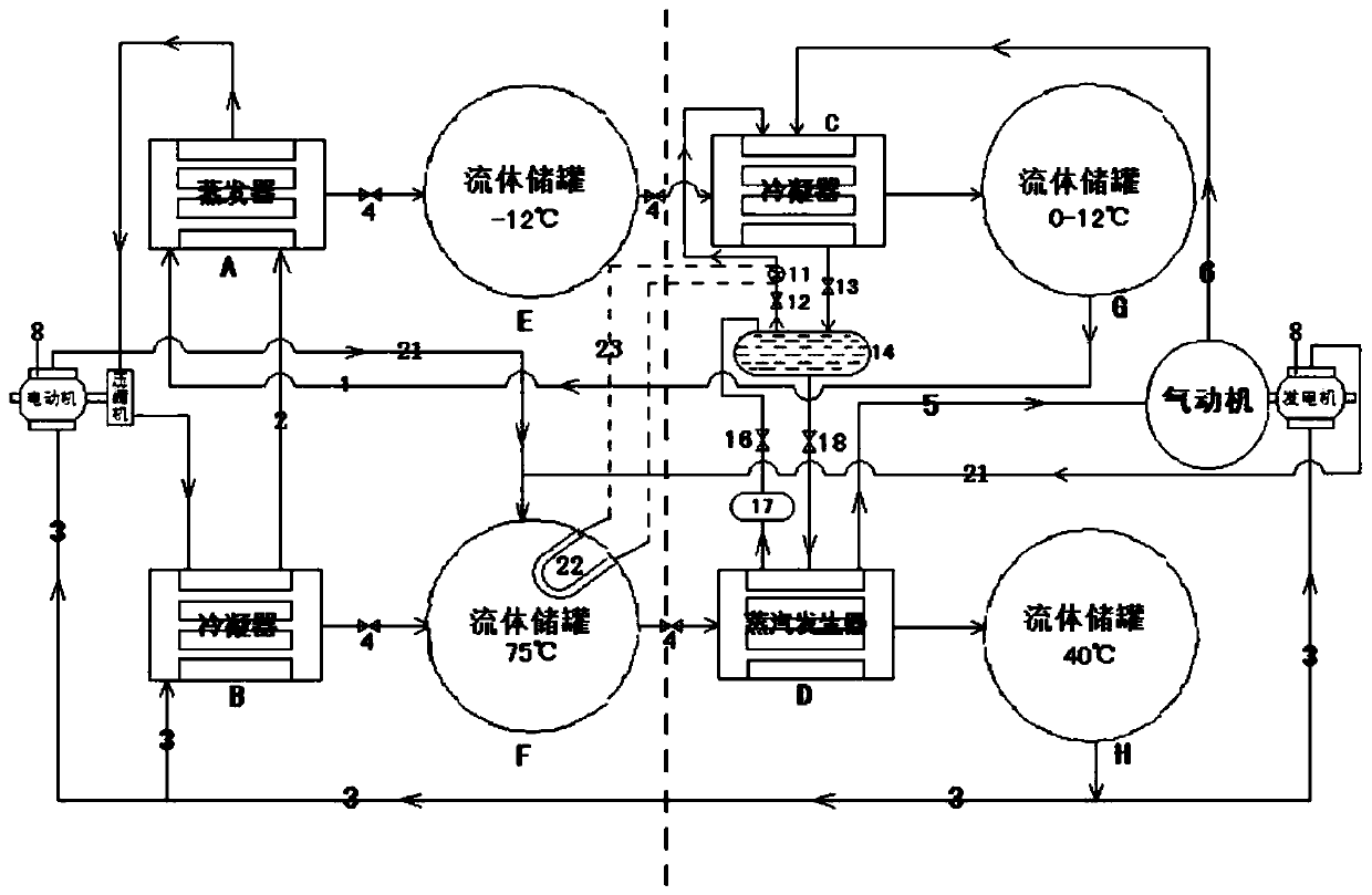
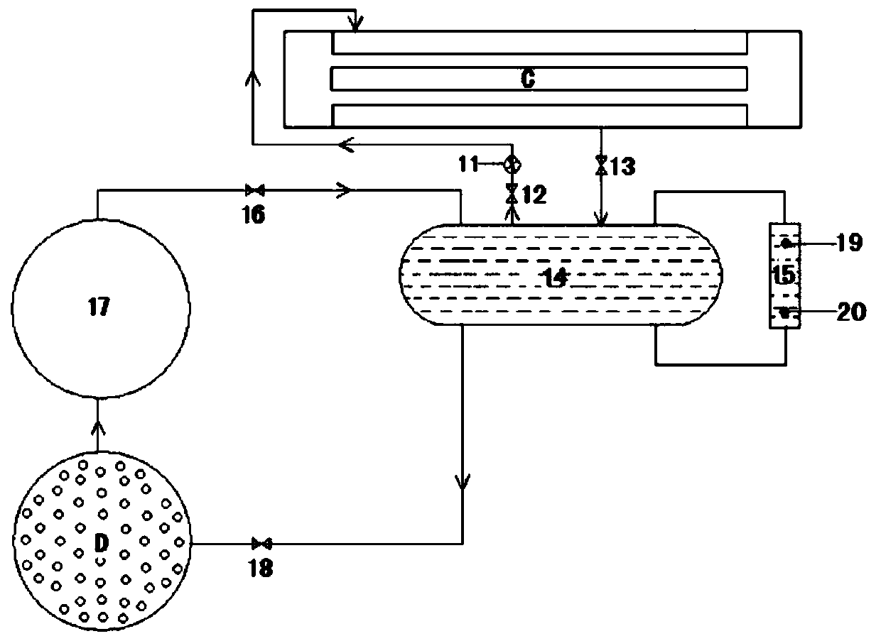
[0065] figure 1 is a schematic diagram of a distributed energy conversion system according to an embodiment of the present invention. Such as figure 1 As shown, the distributed energy conversion system according to an embodiment of the present invention includes: a heat pump I, an air motor J, a circulation loop for supplying salt water to circulate in it, and a circulation loop for supplying water to circulate in it, wherein,

...


PUM


Abstract

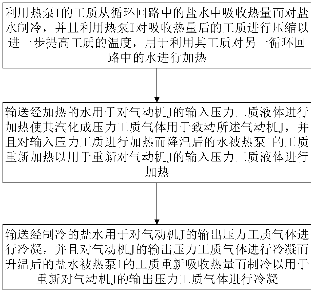
The invention discloses a distributed energy conversion method and system. The distributed energy conversion method comprises the steps that first fluid flowing in a first circulation loop in a circulating mode is refrigerated by using a working medium of a heat pump; a heat pump is used for compressing the working medium to further raise the temperature of the working medium for heating second fluid flowing in a second circulation loop in a circulating mode; the heated second fluid is conveyed to be used for heating an input pressure working medium of an air engine to enable the input pressure working medium to vaporize into pressure working medium gas for actuating the air engine, and after the input pressure working medium is heated and cooled, the second fluid is reheated by the working medium of the heat pump for reheating the input pressure working medium of the air engine, so that the second fluid is cyclically heated and cooled; and the refrigerated first fluid is conveyed to be used for condensing an output pressure working medium of the air engine, and after the output pressure working medium of the air engine is condensed and heated up, the first fluid is re-refrigeratedby the working medium of the heat pump for condensing the output pressure working medium of the air engine, so that the first fluid is cyclically condensed and heated up.

Description

technical field [0001] The present invention relates to the technical field of energy conversion and energy storage, in particular to a distributed energy conversion method and a distributed energy conversion system, which can be used to drive external equipment, such as driving a generator to generate electricity. Background technique [0002] At home and abroad, existing energy storage methods (such as electricity storage methods) include pumped water storage, flywheel energy storage, chemical battery energy storage, compressed air energy storage, etc., but the energy efficiency ratio of the above methods is low, and generally It will not exceed 0.8, and the required investment is large. In addition, in the systems implementing these methods, some heat and cold energy that can be reused are also discharged from the system as waste heat, resulting in energy waste and lower energy efficiency ratio. [0003] In addition, some existing energy storage methods need to use speci...

Claims


Application Information

Patent Timeline
IPC IPC(8): F01K17/02F01K13/00F01K3/08F01K3/00F01K25/10F01K27/00F25B27/02F25B30/02F25B41/00F25B41/04F25B41/20F25B41/40
CPCY02A30/274F25B27/02F01K17/02F25B30/02F01K25/10F01K3/08F25B29/00F25B41/20F01K13/00F01K27/02F25B2339/041F25B2339/047
Inventor 孙诚刚
Owner 孙诚刚
Learn More