
Water environment ecological restoration system

An ecological restoration and water environment technology, applied in the field of environmental protection and water affairs, can solve the problems of high cost, high operating cost, easy to be washed away by water, etc., and achieve the effect of reducing equipment cost

Inactive Publication Date: 2019-05-28
刘彦光
View PDF0 Cites 0 Cited by
  • Summary
  • Abstract
  • Description
  • Claims
  • Application Information

AI Technical Summary

Problems solved by technology

[0002] Generally speaking, when the water body of rivers, rivers, and lakes is treated, the water body will be pumped into the water treatment device for purification treatment, and the water body will be discharged into the environmental water body after being treated by microorganisms or chemicals, but this method requires high-lift water pumps and To acquire land, its cost is very expensive, and the operating cost is also high
[0003] At present, many microorganisms are used to treat the water bodies of rivers, rivers, and lakes. However, when encountering high tides, low tides, and fast-flowing one-way rivers, the bacteria cannot fully contact the pollutants in the water body to produce effects and are easily washed away by water.

Method used


Image

  • Water environment ecological restoration system
  • Water environment ecological restoration system
  • Water environment ecological restoration system

Examples


Embodiment Construction

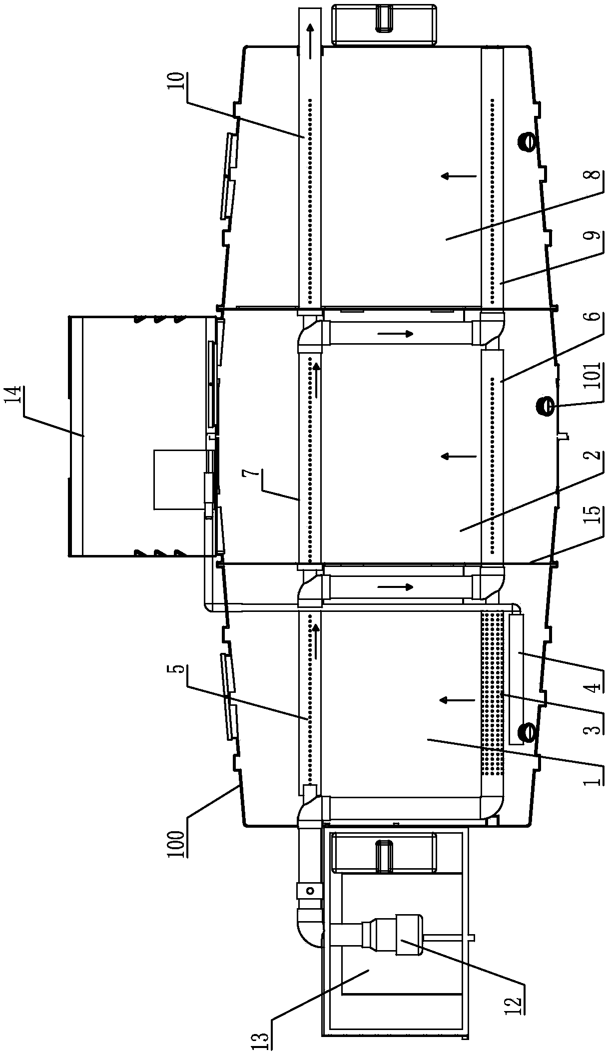
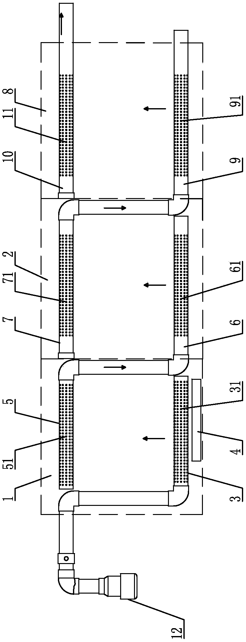
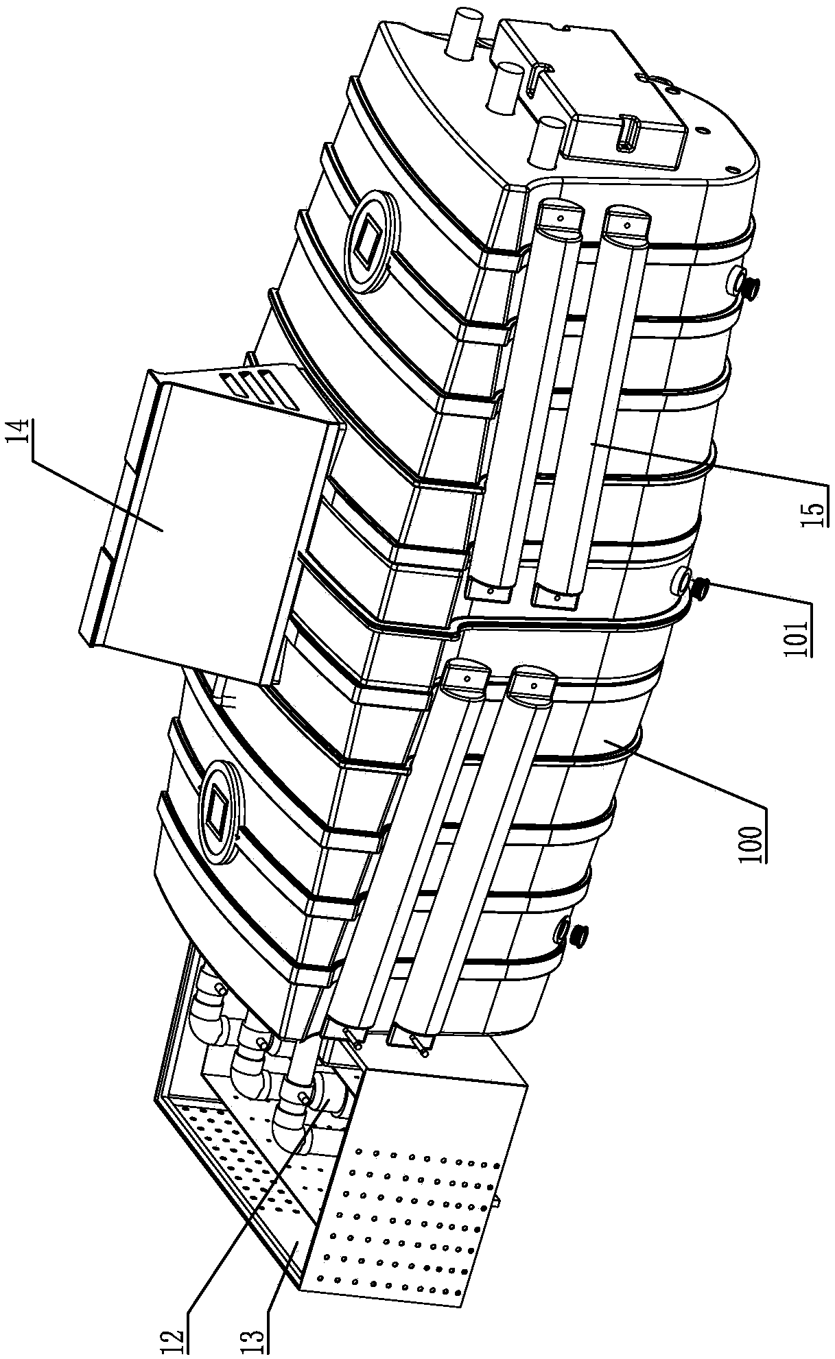
[0028] Such as figure 1 with figure 2 The water environment ecological restoration system shown includes a front chamber 1 and a rear chamber 2 . The front-stage chamber 1 and the rear-stage chamber 2 are arranged side by side from left to right, but the two are separated by a partition 15 and are not permeable to each other. Both the front-stage chamber 1 and the rear-stage chamber 2 are filled with biological fillers not shown in the figure. In the embodiment, both the front-stage chamber 1 and the rear-stage chamber 2 are substantially closed, that is, they are air-tight and water-tight except for necessary pipelines.

[0029] A front-stage water inlet pipe 3 and an aeration component 4 are arranged at the bottom of the pre-chamber 1 . The pre-stage water inlet pipe 3 is introduced from the front-stage chamber 1 to supply water at the bottom. The aeration part 4 is generally a microporous aeration pipe, located below the pre-stage water inlet pipe 3, which can release c...


PUM


Abstract

The invention discloses a water environment ecological restoration system which comprises a front-stage cavity, a back-stage cavity, a front-stage water inlet pipe, an aeration component, a front-stage water and gas collecting pipe, a back-stage water and gas inlet pipe and a back-stage water and gas collecting pipe; the front-stage cavity and the back-stage cavity are separated side by side; a filler filled with microorganisms is charged in each of the front-stage cavity and the back-stage cavity; the front-stage water inlet pipe and the aeration component are arranged at the bottom of the front-stage cavity; the front-stage water and gas collecting pipe is arranged on the top of the front-stage cavity; the back-stage water and gas inlet pipe is arranged at the bottom of the back-stage cavity; the front-stage water and gas collecting pipe and the back-stage water and gas inlet pipe are communicated with each other through a pipeline; and the back-stage water and gas collecting pipe isarranged in the back-stage cavity and leads to the external of the back-stage cavity. The water environment ecological restoration system saves the equipment and operation costs, and can fully utilize the condition that water, gas and the microorganisms can fully contact with one another with a little kinetic energy to solve the problem of flowing water microorganism river treatment, achieves thepurposes of quickly eliminating black and odor as well as rapidly eliminating sludge and pollutants, enables organisms to be restored and realizes the effect of replacing desilting with pollution control. The water environment ecological restoration system can be applied to water environment ecological restoration treatment.

Description

technical field [0001] The invention relates to the fields of environmental protection and water affairs, in particular to a water environment ecological restoration system. Background technique [0002] Generally speaking, when the water body of rivers, rivers, and lakes is treated, the water body will be pumped into the water treatment device for purification treatment, and the water body will be discharged into the environmental water body after being treated by microorganisms or chemicals, but this method requires high-lift water pumps and To acquire land, its cost is very expensive, and the operating cost is also very high. [0003] At present, many microorganisms are used to treat the water bodies of rivers, rivers, and lakes. However, when encountering high tides, low tides, and fast-flowing one-way rivers, the bacteria cannot fully contact the pollutants in the water body to produce effects and are easily washed away by water. . [0004] In order to overcome these ...

Claims


Application Information

Patent Timeline
IPC IPC(8): C02F3/34
Inventor 刘彦光刘建勋刘灵芝
Owner 刘彦光
Learn More