Structural part and overload protection mechanism of torque measuring device

A technology of torque measurement and overload protection, which is applied in the direction of measuring devices, torque measurement, power measurement, etc., can solve the problems of high precision machining of coaxial holes, lack of protection of strain bodies, difficulty in uniform spacing control, etc., to achieve The effect of improving service life, improving accuracy and reducing cost

Pending Publication Date: 2019-05-28
溱者(上海)智能科技有限公司
View PDF3 Cites 4 Cited by
  • Summary
  • Abstract
  • Description
  • Claims
  • Application Information

AI Technical Summary

Problems solved by technology

This method has high requirements on the machining accuracy of the coaxial hole, and at the same time, due to the flexibility of the sensor, the machining of the coaxial hole is more difficult
In addition, when the pin 503 is assembled, the distance between the pin 503 and the through hole 103 on the circumference is difficult to control evenly, which may cause the distance in one direction to be too large to protect the strain body 303, and the distance in the other direction to be too small to protect the strain in advance Body 303
[0008] Through the analysis of the above similar patents, it can be seen that the existing technical solutions have certain problems in solving the bending moment resistance of the sensor and the realization of overload protection.

Method used


Image

  • Structural part and overload protection mechanism of torque measuring device
  • Structural part and overload protection mechanism of torque measuring device
  • Structural part and overload protection mechanism of torque measuring device

Examples


Embodiment 1

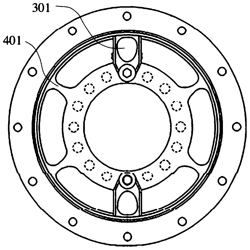
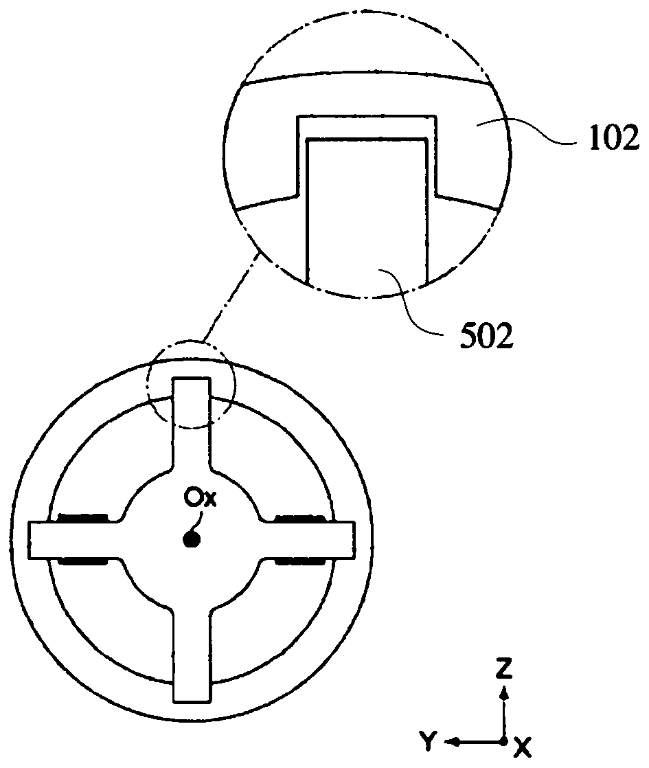
[0084] The structure of this embodiment is Figure 5 As described, the anti-bending moment connecting portion is a straight connecting piece 410, and the straight connecting piece 410 may also be called a connecting beam. The structure is composed of an outer ring 110, an inner ring 210, a strain body 310 and a straight connecting piece 410. The above-mentioned components are obtained by integral processing and molding of the same material. In order to improve the rigidity of the robot against bending moment, the straight connecting piece 410 is processed by wire cutting or laser cutting. The outer ring 110 and the inner ring 210 are concentric circles, and the gap between the two is roughly a circular ring. The straight connecting piece 410 connects the outer ring 110 and the inner ring 210, that is, the straight connecting piece 410 is arranged on the outer ring 110 and the inner ring 210. The gap position. The distribution requirement of the straight connecting member 410 i...

Embodiment 2

[0092] The function of the anti-bending moment connection part is to resist the bending moment. It is required that the size in the axial direction of the structural member is as large as possible, that is, as "thick" as possible, so that it has higher bending rigidity; and in the other direction, it is required It reduces the impact on the measured torque as much as possible, that is, it is required that the bending moment connection part is as thin as possible in this direction; this is a contradiction. Moreover, it is not only difficult to process the bending moment-resistant connection part to be very thin, but also has the risk of fracture. Under the processing conditions of acceptable cost, the minimum thickness of the bending moment connection part is about 0.5mm.

[0093] In order to solve the above contradiction, such as Picture 10 As shown, the anti-bending moment connecting portion is processed into a folding connecting piece 420 connected between the outer ring 110 a...

Embodiment 3

[0095] Such as Picture 11 versus Picture 12 As shown, this embodiment is another alternative to improve the bending moment resistance of the torque measuring device. A detachable connector 430 is added between the outer ring 110 and the inner ring 210. One end of the body 431 of the connector 430 is fixed to the outer ring 110 by a screw 433, the other end of the body 431 is mounted with a roller 432, and the shaft of the roller 432 is mounted on the Inside the body 431. The rolling surface of the roller 432 is in contact with a surface of the inner ring 210, which can appropriately increase the preload contact force. The axis of the roller 432 extends along the radial direction of the inner ring, that is, the axis of the roller 432 and the rotation axis of the torque measuring device are perpendicular and intersect. When the outer ring 110 and the inner ring 210 move relative to each other due to torque, the roller 432 rolls on the surface of the inner ring 210 without affe...


PUM

PropertyMeasurementUnit
thicknessaaaaaaaaaa

Abstract

The invention provides a structural part and overload protection mechanism of a torque measuring device. The structural part comprises an outer ring, an inner ring and a first connecting part; the structural part further comprises a second connecting part arranged between the outer ring and the inner ring; the second connecting part is configured to be used for resisting bending moment borne by the torque measuring device when the structural part is installed on the torque measuring device. The overload protection mechanism is arranged between the outer ring and the inner ring, and comprises aconcave part and a convex part, the head portion of the convex part is contained in the concave part, and a gap is formed between the opposite side faces of the convex part and the concave part. Theproblem that the bending moment resistance of an existing torque measuring device is poor is solved. When a load is too large, the overload protection mechanism can effectively solve the damage of overload to a strain body in the movement process of a robot, the service life of the torque measuring device is prolonged, and the cost is reduced.

Description

Technical field [0001] The invention relates to a torque measuring device, in particular to a structural component and an overload protection mechanism of a torque measuring device, and belongs to the technical field of robot sensors. Background technique [0002] The torque sensor installed at the robot joint is used to measure the torque in one of the rotation directions. The torque sensor usually has one or more strain bodies. The torque that the sensor bears is calculated by measuring the deformation of the strain body. When designing the sensor, through the design of the structure, the deformation of the strain body and the torque are in an approximate linear relationship. The deformation of the strain body can be measured by resistive (strain gauge), capacitive, electromagnetic and optical methods. [0003] The torque sensor is installed at the output of the robot joint, which can directly measure the output torque of the joint. Compared with the method of calculating the jo...

Claims


Application Information

Patent Timeline
Patent Type & Authority Applications(China)
IPC IPC(8): G01L3/00B25J13/08
Inventor 陈鸿格莫喜先
Owner 溱者(上海)智能科技有限公司
Why Eureka
Try Eureka