Power supply and data transmission device for pipe network monitoring equipment and construction application method

A technology of data transmission device and monitoring equipment, which is applied in the direction of measuring device, circuit device, battery circuit device, etc., which can solve the problems of inconvenient management work, affecting the normal monitoring work of the water supply system, increasing the use and management costs, etc.

Active Publication Date: 2019-05-28
重庆飞扬测控技术研究院有限公司
View PDF13 Cites 0 Cited by
  • Summary
  • Abstract
  • Description
  • Claims
  • Application Information

AI Technical Summary

Problems solved by technology

The use of 220V power supply will increase the difficulty of construction due to the need to lay power supply wires, especially when the pipeline is far away from the 220V power line, it will bring inconvenience to the construction and increase the construction cost. Above the ground, it not only affects the coordination of the surrounding environment, but also has a certain impact on the usual safety management; if the battery is used for power supply, the battery needs to be charged or replaced at regular intervals during use, because each terminal signal The power consumption of the battery is different from the power consumption difference, so the daily inspection and maintenance management of the battery must become a normal state, which will bring great inconvenience to the usual management and greatly increase the use and management costs, especially for the management personnel When you forget to charge due to various reasons, the 3G or wireless transmission module, water pressure and water flow monitoring equipment, etc. will not work normally, which will affect the normal monitoring work of the water supply system
[0004] In the prior art, most of the pipeline wells where related equipment is installed are located in remote and remote places, especially some pipeline wells are distributed in the middle of the road, and it is impossible to use solar energy or wind energy to provide power for related electrical equipment, so the daily management work will be even more inconvenient
In addition, in order to increase the road strength and pedestrian safety, the pipeline well adopts iron manhole cover. Since the iron manhole cover will cause serious wireless signal shielding, the wireless transmission module needs to increase the power to realize the connection with the base station. At the same time, the humidity in the pipeline well is high, and the battery efficiency It will also decrease, which will inevitably lead to faster power consumption. If there is no supplementary power supply, the service life of the battery will be reduced, which will cause the electrical equipment to no longer work in a short period of time.
Existing monitoring equipment used for water pressure and water flow data in the pipeline needs to be installed at the side of the pipeline, which has the disadvantage of high cost
In the existing pipeline wells, there is no equipment that can monitor the internal water in real time. In practical applications, due to pipe bursts or leakage, water from the rainstorm road area leaks into the well, and excessive water accumulation in the pipeline well occurs. For a long time, not only it is easy to cause damage to related instruments and meters due to flooding, and they cannot work normally, but also cause water sources to be polluted
In the existing technology, in order to prolong the service life of the battery, it is usually implemented by extending the data transmission time interval, such as transmitting data every 15 minutes or an hour, so that the management side cannot obtain the complete operation data of the pipe network. management will not be able to better analyze the decision

Method used


Image

  • Power supply and data transmission device for pipe network monitoring equipment and construction application method
  • Power supply and data transmission device for pipe network monitoring equipment and construction application method
  • Power supply and data transmission device for pipe network monitoring equipment and construction application method

Examples


Embodiment Construction

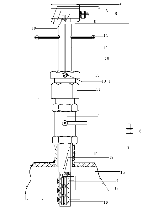
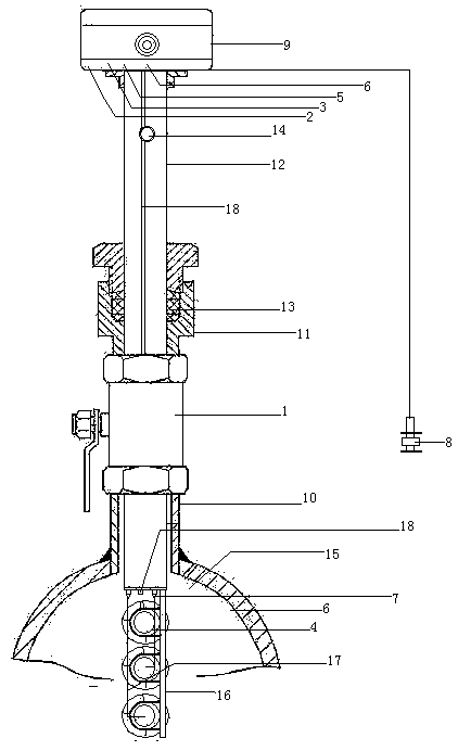
[0023] figure 1 , 2 As shown in , the power supply and data transmission device used by the pipeline network monitoring equipment includes ball valve 1, AC to DC power supply module 2, lithium battery 3, water flow generator 4, single-chip microcomputer module 5, wireless transmission module 6, pagoda-shaped wire sealing screw 7. Water accumulation detection head 8, water pressure probe 19, component box 9, also has connecting pipe 10, locking pipe 11, telescopic pipe 12, locking nut 13, handle rod 14, the lower end of connecting pipe 10 is installed in the pipe network The outer side of the upper end opening of the water supply pipe 15, the outer side of the upper end of the connecting pipe 10 has an external thread, the inside of the connecting pipe 10 has an internal thread, the lower end of the ball valve 1 is installed on the upper end of the connecting pipe 10, and the upper volume of the locking pipe 11 is larger than the lower volume The upper and lower parts of the l...


PUM


Abstract

The invention relates to a power supply and data transmission device for pipe network monitoring equipment, which comprises a ball valve, an alternating current to direct current power supply module,a lithium storage battery, a water flow generator, a singlechip microcomputer module, a wireless transmission module, a pagoda-shaped lead sealing screw rod, a water accumulation detection head and anelement box, a connecting pipeline, a locking pipe, a telescopic pipe, a locking nut and a handle rod, the ball valve, the water flow generator, the singlechip microcomputer module, the pagoda-shapedlead sealing screw rod, the connecting pipeline, the locking pipe, the telescopic pipe, the locking nut and the handle rod are installed together, wherein the alternating current to direct current power supply module, the lithium storage battery, the singlechip microcomputer and the wireless transmission module are arranged in the element box, the water accumulation detection head are arranged onan alarm height of a pipeline shaft wall through the a screw rod and a nut; the method includes six steps. The device does not need the supply of external energy, is convenient to install, does not affect the water supply, can effectively utilize the water flow in the pipeline to generate electricity, and saves the use cost.

Description

technical field [0001] The invention relates to the technical field of water supply supporting equipment, installation and application, in particular to a power supply and data transmission device and a construction application method for pipe network monitoring equipment. Background technique [0002] In the prior art, no matter in the water supply of the municipal pipe network or the water supply of the pipe network in the community (such as the secondary pressurized water supply system of the community), it is necessary to grasp the data of the water pressure and water flow in the pipeline, so as to formulate the water supply department. Relevant control strategies, or directly control the working mode of the water supply system through the received water pressure and water flow data (for example, if the water flow and water pressure in the received user pipeline are low, the water supply system will increase the water supply under the action of its control system, such as...

Claims


Application Information

Patent Timeline
IPC IPC(8): G01R31/00H02J7/32G08C17/02G08C19/00
Inventor 薛金山
Owner 重庆飞扬测控技术研究院有限公司
Why Eureka
Try Eureka