High-voltage isolation ring device of gate drive circuit

A gate drive circuit and high-voltage isolation technology, applied in circuits, electrical components, semiconductor devices, etc., can solve problems such as reliability, high depletion electric field, and early failure of devices, so as to improve withstand voltage stability and reduce electric field strength , Improve the effect of product reliability

Pending Publication Date: 2019-05-28
SHANGHAI HUAHONG GRACE SEMICON MFG CORP
View PDF7 Cites 3 Cited by
  • Summary
  • Abstract
  • Description
  • Claims
  • Application Information

AI Technical Summary

Problems solved by technology

When the device withstands voltage, there is often a relatively high depletion electric field in the chan

Method used


Image

  • High-voltage isolation ring device of gate drive circuit
  • High-voltage isolation ring device of gate drive circuit

Examples


Embodiment Construction

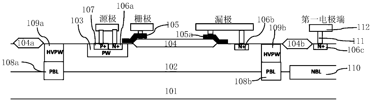
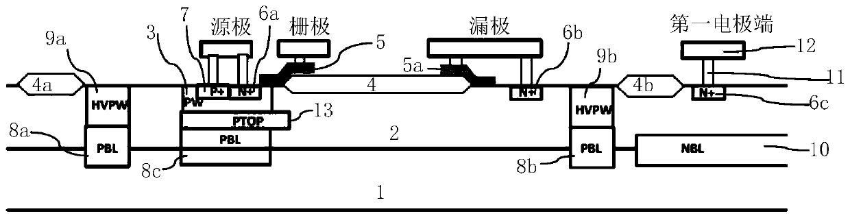
[0061] Such as figure 2 Shown is a cross-sectional structure diagram of the high-voltage isolation ring device of the gate drive circuit of the embodiment of the present invention. The high-voltage isolation ring device of the gate drive circuit of the embodiment of the present invention is composed of LDMOS, including:

[0062] A P-type substrate 1 , an N-type epitaxial layer 2 is formed on the surface of the P-type substrate 1 .

[0063] A P-type buried layer and an N-type buried layer 10 are formed in selected regions of the interface between the P-type substrate 1 and the N-type epitaxial layer 2 .

[0064] The P-type buried layer includes a first P-type buried layer 8a, a second P-type buried layer 8b and a third P-type buried layer 8c.

[0065] A first high-voltage P well 9a is formed in the N-type epitaxial layer 2 between the top surface of the first P-type buried layer 8a and the top surface of the N-type epitaxial layer 2. A second high voltage P well 9b is formed...


PUM


Abstract

The invention discloses a high-voltage isolation ring device of a gate drive circuit, which consists of an LDMOS (Laterally Diffused Metal Oxide Semiconductor), and first to third P-type buried layersand an N-type buried layer are formed on the interface of a P-type substrate and an N-type epitaxial layer; high-voltage N wells are formed at the top of the first P-type buried layer and the top ofthe second P-type buried layer, an area between the two high-voltage N wells is a forming area of a unit structure of the LDMOS, the bottom of a P well of the unit structure of the LDMOS comprises a P-type top injection layer and a third P-type buried layer which are longitudinally connected together, and the device is of a non-isolated structure. The second side of the P-type top injection layertransversely extends into a drift region and covers the first side surface of the drain region field oxide from the bottom, the electric field intensity of the bottom of the first side surface of thedrain region field oxide is reduced by combining the non-isolated structure and the extending structure of the P-type top injection layer, and the voltage withstanding stability and the product reliability of the device are improved. The voltage withstanding stability and the product reliability of the device can be improved.

Description

technical field [0001] The invention relates to a semiconductor integrated circuit, in particular to a high-voltage isolation ring device of a gate drive circuit. Background technique [0002] Gate drive circuits often need to drive high-side power devices and low-side power devices at the same time. The voltage difference between the high-voltage side and the low-voltage side is large, and the difference between the two can reach more than 600V in some applications. In this way, for example, in the application of the high-voltage side circuit for motor driving, it is necessary to set a high-voltage isolation ring in the gate drive circuit to realize the isolation between the high-voltage side and the low-voltage side, and to set a level conversion circuit to realize the isolation between the high-voltage side and the low-voltage side. Level shift between. In the existing structure, high voltage LDMOS (HVLDMOS) is usually used to simultaneously satisfy the functions of isol...

Claims


Application Information

Patent Timeline
IPC IPC(8): H01L29/78H01L29/06H01L21/265
Inventor 王惠惠
Owner SHANGHAI HUAHONG GRACE SEMICON MFG CORP
Why Eureka
Try Eureka