Implantable shaftless heart pump based on gradual change of flow passage

A heart pump and flow channel technology, used in medical science, prostheses, suction devices, etc., can solve the problems of blood cells being easily cut to broken, red blood cells damaged, and high shear force, so as to reduce the probability of cutting blood cells and reduce The probability of thrombosis, the effect of preventing the formation of thrombosis

Active Publication Date: 2019-05-31
HOHAI UNIV +1
View PDF10 Cites 7 Cited by
  • Summary
  • Abstract
  • Description
  • Claims
  • Application Information

AI Technical Summary

Problems solved by technology

[0002] The structures of the existing known vane heart pumps mainly include axial flow type and centrifugal type. In these two kinds of vane heart pumps, there is inevitably a gap between the tip of the vane and the inner wall of the flow channel, forming a large shear force. Damage red blood cells, causing adverse consequences such as coagulation and thrombus
For example, Chinese patent application CN 105169504A discloses a magnetic-fluid coupling passive suspension axial flow blood pump, which adopts a jujube core-shaped cross-sectional structure, has a small flow area between the inlet and outlet, and has a large contact area between the blood and the surface of the impeller and the inner wall of the flow channel. The volume of the impeller chamber is large, the heat generated by the blades is large, and it is easy to cause adverse consequences such as thrombus; Chinese patent application 201110366578.5 discloses a compact axial-flow magnetic levitation artificial heart pump. Although the structure is compact, the flow area is small and requires A higher motor speed can achieve the required blood flow and blood pressure. At a higher speed, the blood cells are more likely to be cut to pieces, which intensifies the symptoms of hemolysis and reduces the physiological function of the blood; at the same time, increasing the speed will bring about a large amount of heat. , high energy consumption and other issues

Method used


Image

  • Implantable shaftless heart pump based on gradual change of flow passage
  • Implantable shaftless heart pump based on gradual change of flow passage
  • Implantable shaftless heart pump based on gradual change of flow passage

Examples


Embodiment Construction

[0018] The specific implementation manners of the present invention will be further described in detail below in conjunction with the drawings and embodiments.

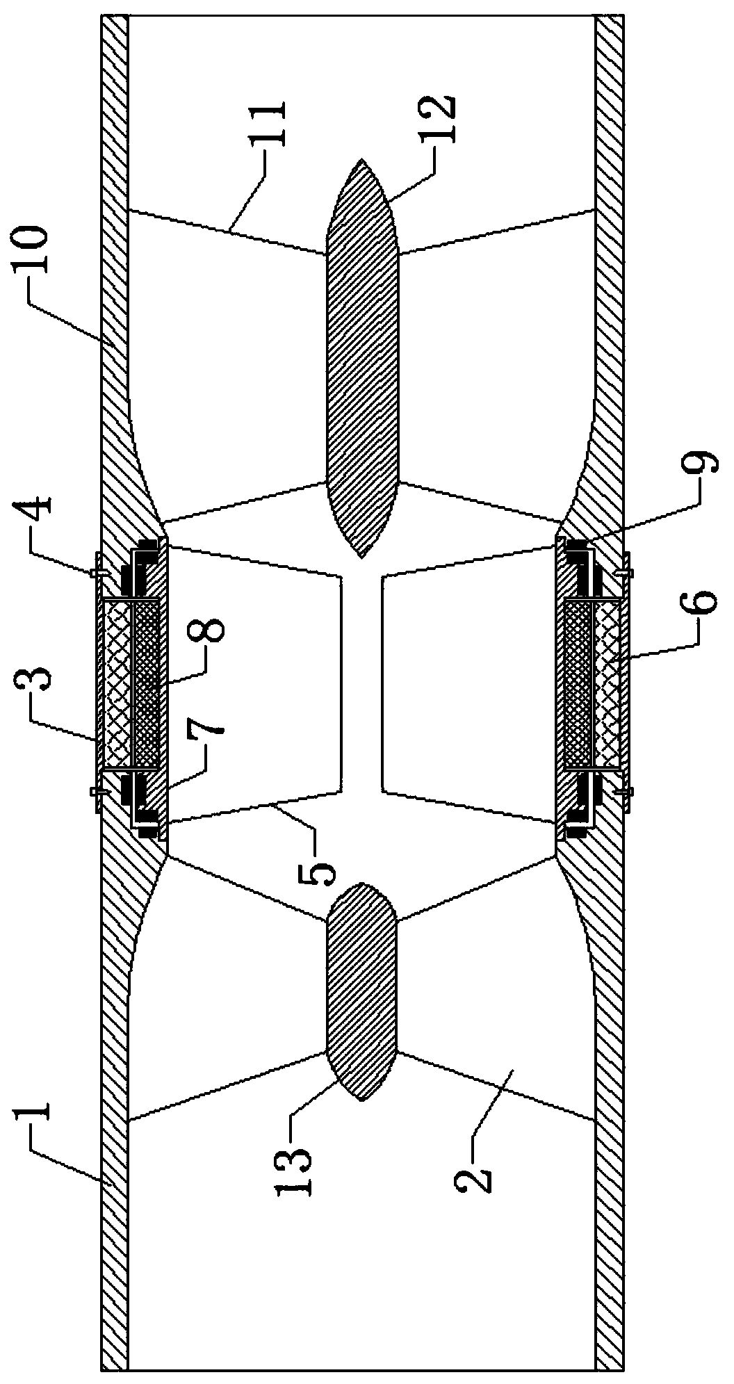
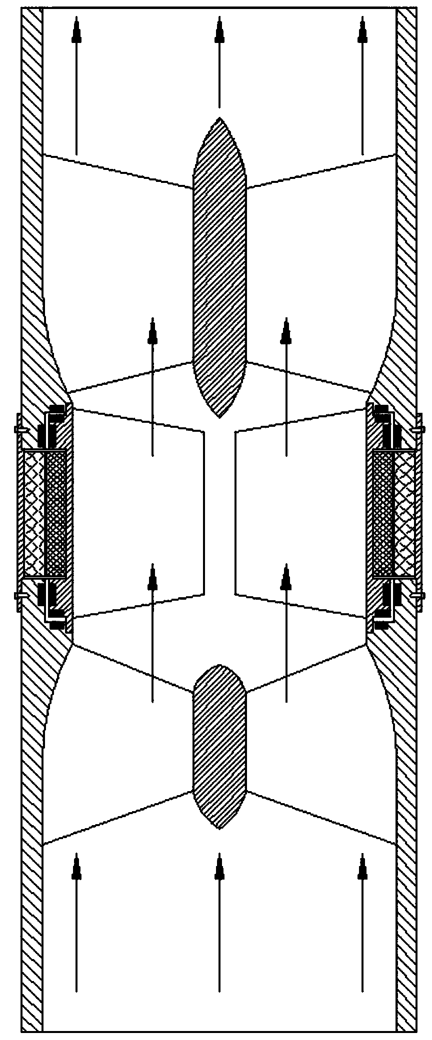
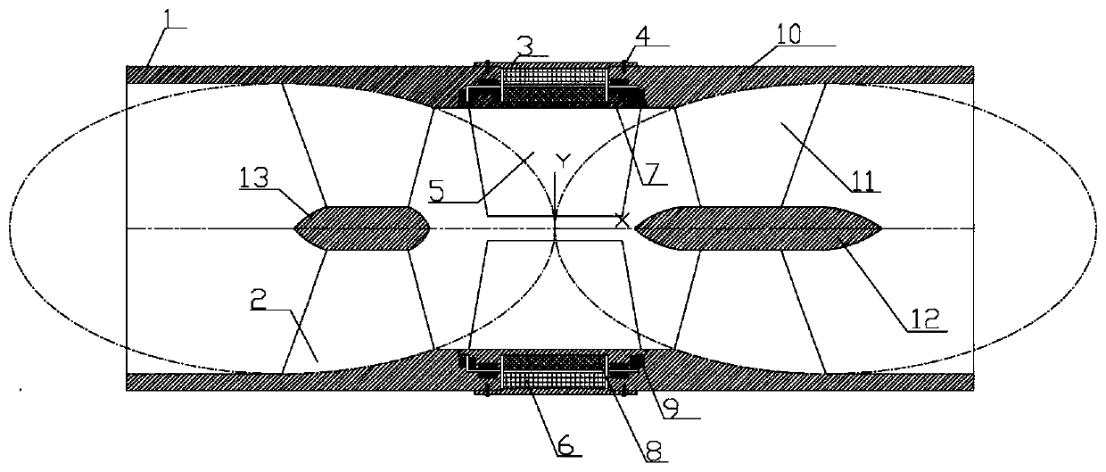
[0019] Example. combine Figure 1-3 , an implantable shaftless heart pump based on the gradual change of the flow channel proposed by the present invention, including the flow channel inlet housing 1, the stator 3 and the flow channel outlet housing 10 are fixedly connected in sequence in the axial direction, and the flow channel inlet housing 1 and the flow channel The inner wall of the housing cavity of the channel outlet housing 10 is respectively provided with a straight-through section, and the inner ports of the straight-through section are transitionally connected with the outer ports of the constricted section, and the inner ports of the constricted section are respectively arranged on the outer surface of the stator 3. Port; the molded line of the inner wall of the shell cavity of the runner inlet shell 1 is...


PUM


Abstract

The invention relates to an implantable shaftless heart pump based on the gradual change of a flow passage. The implantable shaftless heart pump is characterized by comprising a flow passage inlet shell, a stator and a flow passage outlet shell, wherein the flow passage inlet shell, the stator and the flow passage outlet shell are sequentially and axially fixedly connected. The inner wall parts ofshell cavities of the flow passage inlet shell and the flow passage outlet shell are respectively provided with straight-through sections.The inner ports of the straight-through sections are respectively in transition connection with the outer ports of contraction sections, and the inner ports of the contraction sections are respectively arranged at the outer ports of the stator.Profile lines ofthe inner wall parts of the shell cavities of the flow passage inlet shell and the flow passage outlet shell are elliptical. The contraction sections of the inner diameters of the flow passage inlet shell and the flow passage outlet shell are arranged near one side of the stator. The inner wall of the stator is fixedly provided with a stator coil, the middle part of the stator coil is provided with an impeller rotor, and the impeller rotor is fixed through permanent magnetic suspension bearing shafts at two ends.The implantable shaftless heart pumphas the advantages of small volume, large flowand small heat productivity, and can effectively reduce the probability of thrombus formation.

Description

technical field [0001] The invention belongs to the technical field of fluid machinery and axial flow pumps, in particular to an implantable shaftless heart pump based on gradual change of flow path. Background technique [0002] The structures of the existing known vane heart pumps mainly include axial flow type and centrifugal type. In these two kinds of vane heart pumps, there is inevitably a gap between the tip of the vane and the inner wall of the flow channel, forming a large shear force. Damage red blood cells, resulting in adverse consequences such as coagulation and thrombus. For example, Chinese patent application CN 105169504A discloses a magnetic-fluid coupling passive suspension axial flow blood pump, which adopts a jujube core-shaped cross-sectional structure, has a small flow area between the inlet and outlet, and has a large contact area between the blood and the surface of the impeller and the inner wall of the flow channel. The volume of the impeller chamb...

Claims


Application Information

Patent Timeline
Patent Type & Authority Applications(China)
IPC IPC(8): A61M1/10A61M1/12
Inventor 戴景郑源阚阚陈会向戴杰戴启璠王宏图孟小敏许峰
Owner HOHAI UNIV
Why Eureka
Try Eureka