A delay locked loop and a delay locked method

A delay-locked loop and delay-locked technology, which is applied in the direction of electrical components and automatic power control, can solve problems such as poor accuracy and complex timing of delay-locked loops, and achieve loop stability, simplified debugging, and high reliability.

Active Publication Date: 2019-05-31
VERISILICON MICROELECTRONICS SHANGHAI +1
View PDF19 Cites 5 Cited by
  • Summary
  • Abstract
  • Description
  • Claims
  • Application Information

AI Technical Summary

Problems solved by technology

[0005] In view of the above-mentioned shortcomings of the prior art, the object of the present invention is to provide a delay-locked loop and a delay-locked method, which are used to solve the problems of complex timing and poor accuracy of the delay-locked loop in the prior art.

Method used


Image

  • A delay locked loop and a delay locked method
  • A delay locked loop and a delay locked method
  • A delay locked loop and a delay locked method

Examples


Embodiment 1

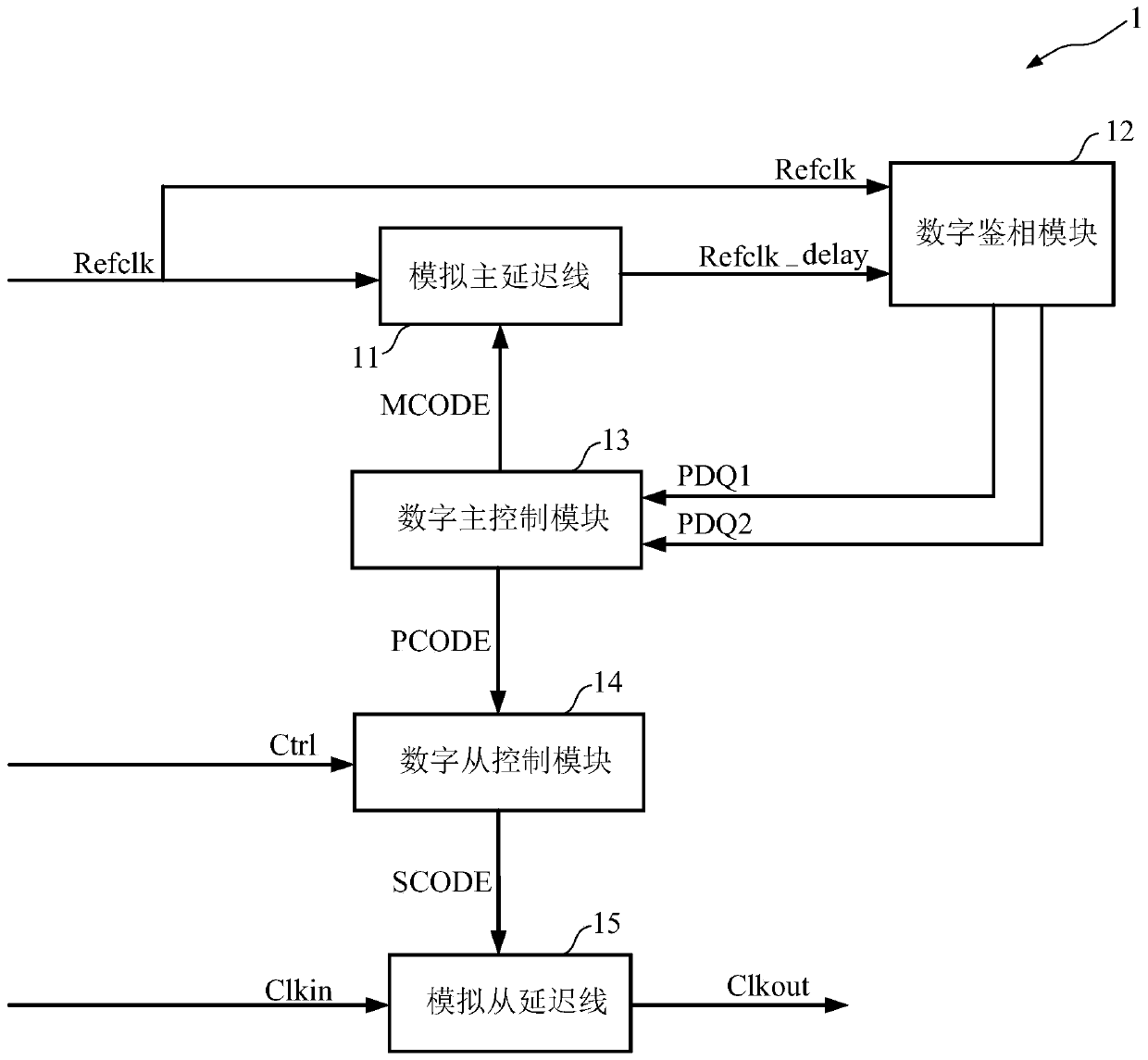
[0054] Such as figure 1 As shown, this embodiment provides a delay-locked loop 1, and the delay-locked loop 1 includes:

[0055] An analog master delay line 11 , a digital phase detection module 12 , a digital master control module 13 , a digital slave control module 14 and an analog slave delay line 15 .

[0056] Such as figure 1 As shown, the analog master delay line 11 is connected to the output end of the digital master control module 13, and receives a reference clock signal Refclk, and controls the reference clock based on the master delay control word MCODE output by the digital master control module 13 Signal Refclk delay.

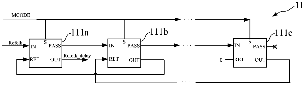
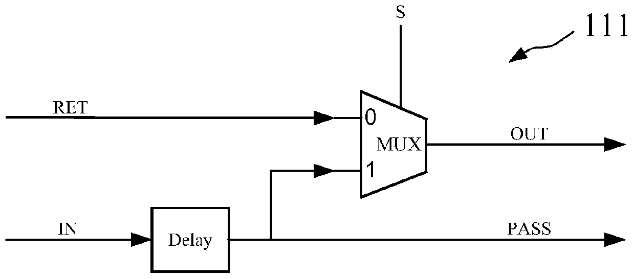
[0057] Specifically, the analog main delay line 11 includes a plurality of analog delay units 111, the first input terminal IN of each analog delay unit 111 is connected to the first output terminal PASS of the previous stage, and the second input terminal RET is connected to the second output terminal of the subsequent stage. The output termina...

Embodiment 2

[0074] This embodiment provides a delay locking method. In this embodiment, the delay locking method is implemented based on the delay locked loop 1 described in Embodiment 1. In practical applications, any structure that can realize the above method is applicable to the present invention The method is not limited to this embodiment. The delay locking method includes:

[0075] 1) Delay the reference clock signal, detect the phase difference of the reference clock signal before and after the delay, and generate a main delay control word based on the detected phase comparison result to adjust the delay time of the reference clock signal until the reference clock signal is delayed A cycle.

[0076] Specifically, such as figure 1 As shown, the reference clock signal Refclk is delayed based on the analog master delay line 11, and the master delay control word MCODE is a set value in an initial state.

[0077] Specifically, such as figure 1 As shown, the phase difference between...


PUM


Abstract

The invention provides a delay locking ring and a delay locking method. The delay locking ring comprises the following steps: delaying an analog main delay line of a reference clock signal based on amain delay control word; enabling the digital phase discrimination module identify the phase difference before and after the reference clock signal delay; the digital main control module is used for adjusting the main delay control word based on the phase difference and assigning the main delay control word corresponding to the delay period to the set delay control word; the digital slave controlmodule takes a set delay control word with a set proportion as a slave delay control word; an analog slave delay line that delays an input clock signal is controlled based on the slave delay control word. Controlling the reference clock signal to be delayed for a period based on the phase-locked loop; assigning the corresponding main delay control word to a set delay control word, multiplying themain delay control word by a set proportion, and adjusting the delay of the input clock signal. According to the invention, the digital phase discriminator and the digital controller are adopted, thereliability is high, and a loop is more stable; and an analog delay line is adopted, so that delay adjustability can be realized, and the circuit debugging difficulty is reduced.

Description

technical field [0001] The invention relates to the field of integrated circuits, in particular to a delay-locked loop and a delay-locked method. Background technique [0002] With the development of modern integrated circuit technology, the scale of the chip continues to increase, and the operating frequency continues to increase. The quality of on-chip clock distribution and clock delay become more and more important. The Delay Locked Loop (DLL) can meet the precise synchronization requirements of the on-chip high-speed clock, eliminate clock delay, realize zero transmission delay, and minimize the deviation between the clock input signal and the internal clock pin of the entire chip. As a very important part of integrated circuit design, delay locked loops have gradually become the focus of attention, and are widely used in various SoC (System on Chip, System on Chip) chips. [0003] In the application of the SDIO (Secure Digital Input and Output, secure digital input an...

Claims


Application Information

Patent Timeline
IPC IPC(8): H03L7/085
CPCY02D10/00
Inventor 王晏清马娜董益灿邢文俊
Owner VERISILICON MICROELECTRONICS SHANGHAI
Why Eureka
Try Eureka