Direct power boundary control method based on three-phase three-throw two-level rectifier

A boundary control and rectifier technology, which is applied in the direction of converting AC power input to DC power output, output power conversion devices, electrical components, etc., to achieve the effect of improving dynamic performance

Active Publication Date: 2019-06-04
CHINA THREE GORGES UNIV
View PDF6 Cites 1 Cited by
  • Summary
  • Abstract
  • Description
  • Claims
  • Application Information

AI Technical Summary

Problems solved by technology

However, most of the papers only study the boundary control schemes of single-phase power electronic converters, and there are few studies on the boundary control of three-phase PWM rectifiers, especially the use of natural switching surfaces

Method used


Image

  • Direct power boundary control method based on three-phase three-throw two-level rectifier
  • Direct power boundary control method based on three-phase three-throw two-level rectifier
  • Direct power boundary control method based on three-phase three-throw two-level rectifier

Examples


Embodiment Construction

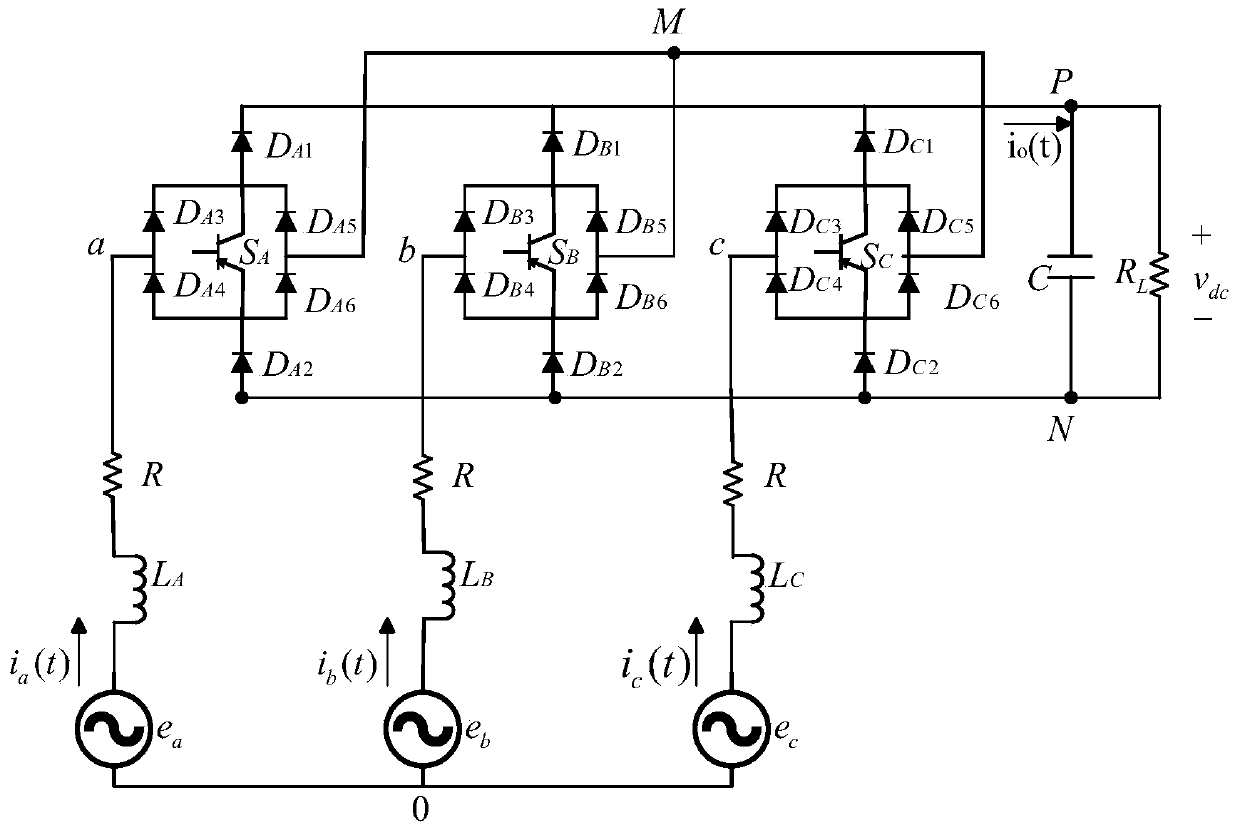
[0026] Step 1: Analyze the working process of the three-phase three-switch two-level rectifier, and use the coordinate transformation to establish the mathematical model of the rectifier under the synchronously rotating dq coordinate system;

[0027] Step 2: Combined with the instantaneous power theory, the mathematical model of the rectifier in the synchronously rotating dq coordinate system is converted into a power model in the dq coordinate system with P and Q as variables;

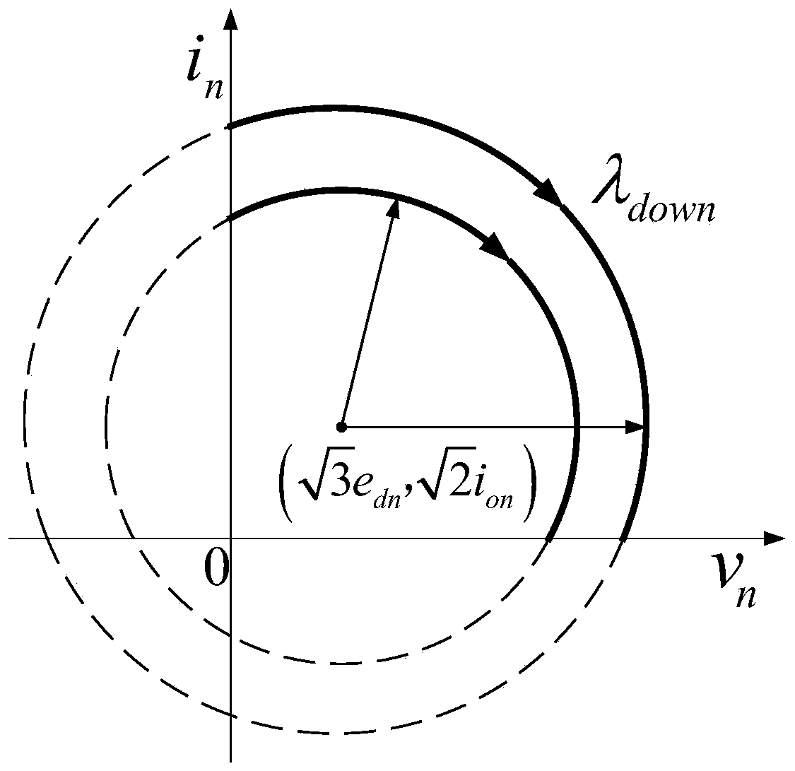
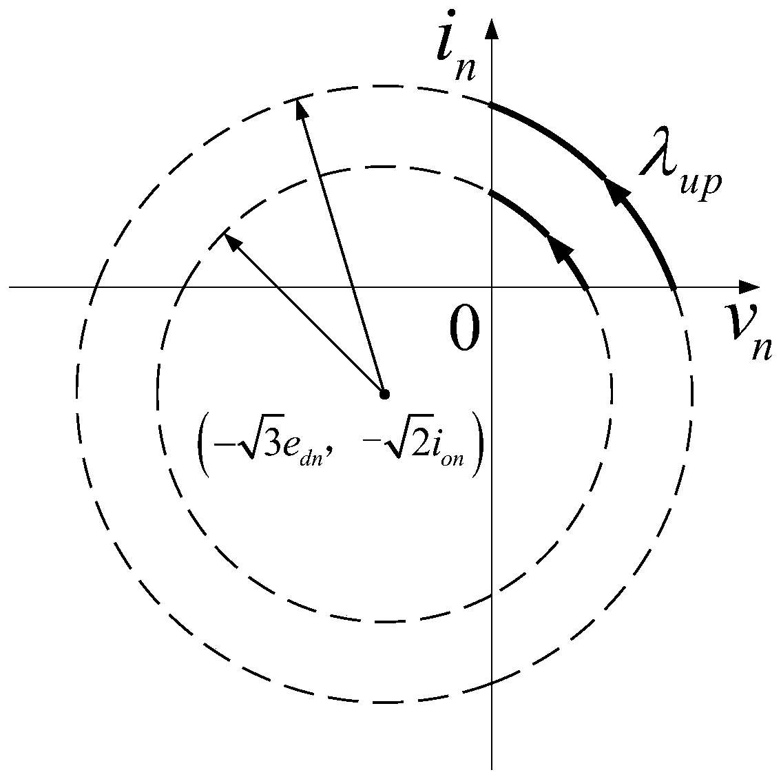
[0028] Step 3: Analyze the boundary control conditions of the three-phase three-switch two-level rectifier, that is, take the DC side voltage as the horizontal axis of the phase plane, and the AC side current as the vertical axis of the phase plane to establish a standard phase plane; in the standard phase plane, The rectifier has different natural trajectories in different states, and the natural trajectories of the rectifier when the AC side current decreases and increases are analyzed;

[0029] Ste...


PUM


Abstract

The invention relates to a direct power boundary control method based on a three-phase three-throw two-level rectifier. A mathematical model of the three-phase three-throw two-level rectifier in a two-phase synchronous rotating coordinate system is established; a power model of the rectifier in the rotating coordinate system is established by combining an instantaneous power theory and a voltage orientation principle; a standard phase plane is established by taking the DC side voltage as the transverse axis and the AC side current as the longitudinal axis, and change of a natural trajectory ofthe rectifier when the AC-side current of the rectifier is decreased and increased in the standard phase plane is analyzed; and on the basis of the power amount, a boundary control condition is usedto crease novel direct power control, a natural switching side of boundary control is selected by taking the natural trajectory of the rectification system, when the AC-side current is decreased and increased, as basis, the natural switching side is used to update output rule of direct power control in a power hysteresis comparator, and finally a direct power boundary control method is obtained. The dynamic performance in the DC side of the three-phase three-throw two-level rectifier can be improved effectively aimed at the abrupt load change in practical application.

Description

technical field [0001] The invention relates to the technical field of three-phase, three-on, two-level rectifier control, in particular to a direct power boundary control method based on a three-phase, three-on, two-level rectifier. Background technique [0002] In recent years, due to the rapid development of the economy, the demand for energy has also increased. Low-carbon energy conservation has become a common requirement of all countries in the world. The green and low-carbon development of electric energy is of great significance to energy conservation and environmental protection. Therefore, how to obtain high-quality electric energy has become the focus of current research. In order to solve the problem of harmonic pollution, PWM technology is introduced into the rectifier to produce a PWM rectifier. , The current distortion rate of the grid side is low. At present, the grid-side current control strategies of three-phase PWM rectifiers are divided into indirect cur...

Claims


Application Information

Patent Timeline
Patent Type & Authority Applications(China)
IPC IPC(8): H02M7/217
Inventor 马辉田鹏辉韩笑田宇
Owner CHINA THREE GORGES UNIV
Why Eureka
Try Eureka