Fibrous structure and 3D preform for a composite part

A fiber structure, prefabricated technology, used in textiles and paper, textiles, fabrics, etc.

Active Publication Date: 2019-06-04
PORCHER INDUSTRIES
View PDF7 Cites 2 Cited by
  • Summary
  • Abstract
  • Description
  • Claims
  • Application Information

AI Technical Summary

Problems solved by technology

[0015] It is also an object of the present invention to provide a method of producing such preforms that solves the problems of previous methods (e.g. electrostatic powder coating)

Method used


Image

  • Fibrous structure and 3D preform for a composite part
  • Fibrous structure and 3D preform for a composite part
  • Fibrous structure and 3D preform for a composite part

Examples


example 1

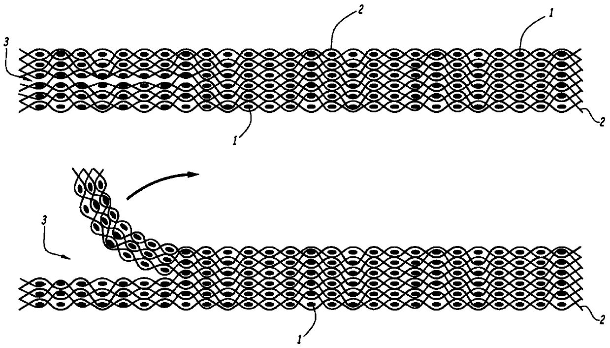
[0102] figure 1 6 consecutive horizontal planes of the woven fabric showing the fibrous structure obtained by 3D weaving, where weft yarn 1 is visible in cross-section and warp yarn 2 is shown longitudinally.

[0103] The fiber structure (on the left side of the diagram) consists of 6 layers of weft yarns and 12 layers of warp yarns. On the right side of the figure, all warp and weft layers are linked. On the left side, the two central weft yarn layers are not bonded together by the warp yarns in the 7 perpendicular planes of the weft yarns, where this is referred to herein as the debonding zone, reference 3.

[0104] Fiber volume ratio: 50%.

[0105] Count of carbon yarn in warp and weft: 3K

[0106] Thickness of the structure (and prefab): about 3mm.

[0107] The warp and weft yarns were carbon yarns impregnated with polyepoxide resin at a weight of approximately 7% of the weight of the complete structure. The structure is laid out in a mold, passed through an oven to s...

example 2

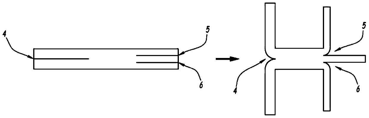
[0112] Based on the principle of Example 1, it is possible to weave according to figure 2 (Left) Fibrous structure comprising a first debonding zone 4 on the left and two debonding zones 5 and 6 on the right. This flat structure (left side of the diagram) can then be deployed in the form of a 3D deployed structure comprising 5 branches (right side of the diagram).

[0113] The warp and weft yarns were carbon yarns impregnated with polyepoxide resin at a weight of approximately 5% of the weight of the complete structure. The structure is laid out in a mold, passed through an oven to soften the resin, and then cooled to create a 3D preform. In the same mold or in another mold, the 3D preform will then be infiltrated or infused with the PEEK matrix to form the final part.

example 3

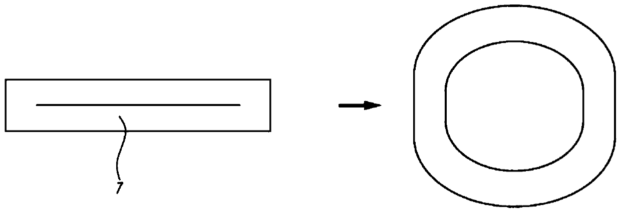
[0115] According to the same principle as Example 1, it is possible to weave according to image 3 (Left) Fibrous structure including a central debonding zone 7 . This flat structure (left-hand diagram) can then be deployed in the form of a hollow 3D or hollow tubular structure (right-hand diagram).

[0116] The warp and weft yarns are carbon yarns impregnated with polyamide resin, the weight of which is approximately 10% of the weight of the complete structure. The structure is laid out in a mold, passed through an oven to soften the resin, and then cooled to create a 3D preform. In the same mold or in another mold, the 3D preform will then be infiltrated or infused with the PEEK matrix to form the final part.

[0117] The debonding embodiment can be varied, for example, by forming the yarns into a warp and combining both types of yarns in the same structure.


PUM

PropertyMeasurementUnit
Thicknessaaaaaaaaaa

Abstract

The preform made of a 3D fibrous structure comprises at least 3 layers (1, 2) of weft yarns and / or warp yarns, the structure being woven as a single part by multilayer weaving between a plurality of layers of warp yarns and a plurality of layers of weft yarns. It comprises a predetermined distribution of points of intersection of warp yarn and weft yarn that are bonded by polymer. The polymer represents a mass of less than or equal to 10%. The preform comprises at least one thermoformed portion in which the warp yarns and the weft yarns are bonded at the intersections thereof by polymer whereat least one of the warp and / or weft yarns bears polymer.

Description

【Technical field】 [0001] The present invention relates to a fibrous structure and a 3D (3-dimensional) preform obtained from this fibrous structure and used to form substrates for composite parts, in particular for high-tech industries such as aeronautics, aerospace and automotive. The invention also relates to a manufacturing method. 【Background technique】 [0002] Composite materials with fabric or fiber reinforcement comprise at least two components: matrix and reinforcement. The matrix that encapsulates and strengthens the reinforcement makes it possible to transmit mechanical stresses via its interfaces. The matrix can also be used to protect the fiber material from aggressions associated with the application environment (chemical, thermal, UV, etc.). The matrix may or may not be organic. Organic matrices fall into two families: thermosets (TS) and thermoplastics (TP). [0003] The second component is the reinforcement, which must provide the mechanical properties o...

Claims


Application Information

Patent Timeline
IPC IPC(8): B29B11/16B29K307/04
CPCB29B11/16B29K2307/04D03D25/005B32B5/06B32B7/12
Inventor 让文森·里奇卡多帕特里克·瓦哈尼阿克休伯特·佩兰威廉·杜塞尼
Owner PORCHER INDUSTRIES
Why Eureka
Try Eureka