Catalyst in-situ regeneration device and method of using the same

An in-situ regeneration and catalyst technology, applied in the field of flue gas denitrification treatment, can solve the problems of timely regeneration, large impact on boiler operation, and large amount of engineering, so as to achieve convenient and fast regeneration, improve regeneration effect, and prolong service life.

Pending Publication Date: 2019-06-07
浙江深度能源技术有限公司
View PDF0 Cites 0 Cited by
  • Summary
  • Abstract
  • Description
  • Claims
  • Application Information

AI Technical Summary

Problems solved by technology

[0007] 1. When the activity of the catalyst is reduced to the point where the denitrification performance cannot be met, the catalyst will be replaced as a whole and cannot be regenerated in time during use;
[0008] 2. It is necessary to remove the invalid catalyst and replace it with a new catalyst, which requires a large amount of work and takes a long time;
[0009] 3. In the process of replacing the catalyst, it is necessary to stop the operation of the denitrification system, which has a great impact on the operation of the boiler;
[0010] 4. The invalid catalyst needs to be sorted according to the structural integrity, activity and other indicators, and the reuse rate of the catalyst is low

Method used


Image

  • Catalyst in-situ regeneration device and method of using the same

Examples


Embodiment Construction

[0035] In order to further understand the invention content, characteristics and effects of the present invention, the following embodiments are given in detail, together with the accompanying drawings. But they do not constitute a limitation of the present invention.

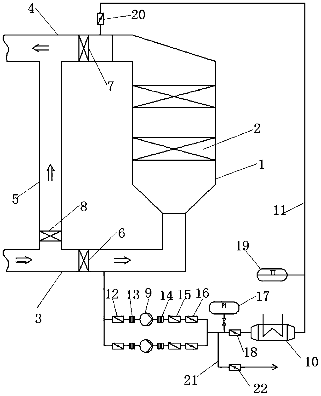
[0036] Such as figure 1 As shown, the present invention provides a catalyst in-situ regeneration device, including a denitration reactor 1, a catalyst 2, a catalyst in-situ isolation system, a catalyst hot air regeneration circulation system and a regeneration waste gas exhaust system; the catalyst 2 is arranged in the denitration reactor 1, the catalyst in-situ isolation system includes an inlet flue 3, an outlet flue 4, a bypass flue 5, a first flue gas baffle door 6, a second flue gas baffle door 7, and a third flue gas The baffle door 8, the intake flue 3 is connected with the inlet of the denitrification reactor 1, the outlet flue 4 is connected with the outlet of the denitrification reactor 1, and the by...


PUM


Abstract

A catalyst in-situ regeneration device and a method of using the same are disclosed, The catalyst is arranged in a denitrification reactor, a first flue gas baffle door is arranged on the inlet flue between the bypass flue and the inlet of the denitrification reactor, a second flue gas baffle door is arranged on the outlet flue between the bypass flue and the outlet of the denitrification reactor,and a third flue gas baffle door is arranged on the bypass flue. One end of a regenerative air duct is connected to the inlet flue between the first flue gas baffle door and the inlet of the denitrification reactor, one end of the regenerative air duct is connected to the outlet flue between the second flue gas baffle door and the outlet of the denitrification reactor, and a regenerative fan anda regenerative wind power heater are arranged on the regenerative air duct in sequence; a regenerative exhaust gas exhaust system is connected to the regenerative air duct of the regenerative fan andthe regenerative wind power heater. The chemical life of SCR catalyst is prolonged, the SCR catalyst is regenerated by hot air in situ, and ammonia bisulfate on the surface of the catalyst is decomposed by at elevated temperature to restore the activity of the catalyst.

Description

technical field [0001] The invention relates to the technical field of flue gas denitrification treatment, in particular to a catalyst in-situ regeneration device and a use method thereof. Background technique [0002] Selective catalytic reduction denitrification technology (SCR) is one of the main methods for post-furnace denitrification treatment of nitrogen oxides in flue gas, and it is also one of the most mature flue gas denitrification technologies at present. The principle of the Selective Catalytic Reduction (SCR) process is that under the action of a catalyst, NH 3 (reducing agent) reacts with nitrogen oxides in flue gas to generate harmless nitrogen and water, thereby removing NOx in flue gas. [0003] The core of selective catalytic reduction denitrification technology (SCR) is a catalytic reaction system, which requires the use of a catalyst, and under the action of the catalyst and the presence of oxygen, NH 3 (Reducing agent) preferentially undergoes reducti...

Claims


Application Information

Patent Timeline
IPC IPC(8): B01D53/96B01D53/86B01D53/56
Inventor 范祥子沈振彬周建华盛振塔季晨
Owner 浙江深度能源技术有限公司
Why Eureka
Try Eureka