Changeable flow channel structure of multifunctional disc type separator capable of changing multiple flow channels

A disc separator and multi-functional technology, applied in the field of fluid machinery, can solve the problems of difficult to clean and block, difficult to process and manufacture, easy to block, etc., to achieve convenient combination and replacement and installation, prevent blockage of flow channels, and easy to clean. Blocking effect

Active Publication Date: 2019-06-07
SHENYANG POLYTECHNIC UNIV
View PDF11 Cites 3 Cited by
  • Summary
  • Abstract
  • Description
  • Claims
  • Application Information

AI Technical Summary

Problems solved by technology

[0002] At present, there are many types and models of disc separators, but generally only one flow channel can be realized, which results in a single function of disc separators and a narrow range of use, and it is impossible to realize multiple uses of one model.
It cannot be realized that one type of machine can realize liquid-liquid two-phase separation and purification, solid-liquid two-phase separation and purification, and liquid-liquid-solid three-phase separation at the same time
[0003] In addition, the disc brackets of the current disc separators are generally of integral structure, and the structure of the flow channel in the disc bracket is relatively complicated, which is easy to clog, and it is not easy to clean the clogs, and it is not easy to process and manufacture, which is not conducive to the realization of multiple Kind of runner
[0004] Moreover, there is generally only one type of disc in the current disc separator, and the structure is single, which is not conducive to realizing multiple flow channels.

Method used


Image

  • Changeable flow channel structure of multifunctional disc type separator capable of changing multiple flow channels
  • Changeable flow channel structure of multifunctional disc type separator capable of changing multiple flow channels
  • Changeable flow channel structure of multifunctional disc type separator capable of changing multiple flow channels

Examples


Embodiment 1

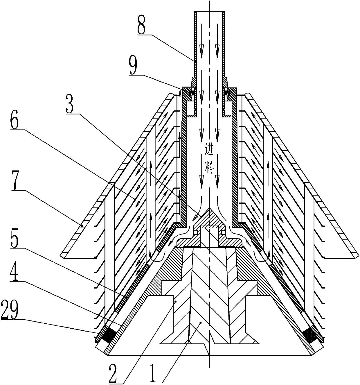
[0042] Such as figure 1 , Figure 5 , Figure 8 , Figure 10 , Figure 11 , Figure 13 , Figure 14 , Figure 15 , Figure 16 , Figure 17 and Figure 18As shown, a variable channel structure of a multi-functional disc separator with multiple channels can be changed, including the drum lower body 2, locking screw cover 3, disc bracket base 4, disc bracket 5, disc 6, disc gland 7 and plug 29, the lock screw cover 3 is located at the upper end of the disc bracket base 4, the lock screw cover 3 has an internal thread, and is screwed on the outer surface of the top of the central shaft 1 through the internal thread. On the thread, the locking screw cover 3 is pressed on the disc bracket base 4, the outer peripheral surface of the joint between the drum lower body 2 and the disc bracket base 4 is a conical surface, and the disc bracket base 4 passes through the inner conical hole sleeve Pressed on the outer conical surface of the lower body 2 of the drum, the lower body 2...

Embodiment 2

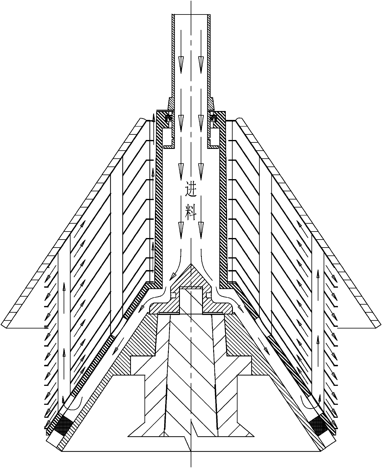
[0045] Such as figure 2 , Figure 4 , Figure 9 , Figure 10 , Figure 12 , Figure 13 , Figure 14 , Figure 15 , Figure 16 , Figure 17 and Figure 18 As shown, a variable channel structure of a multi-functional disc separator with multiple channels can be changed, including the drum lower body 2, locking screw cover 3, disc bracket base 4, disc bracket 5, disc 6, disc gland 7 and plug 29, the lock screw cover 3 is located at the upper end of the disc bracket base 4, the lock screw cover 3 has an internal thread, and is screwed on the outer surface of the top of the central shaft 1 through the internal thread. On the thread, the locking screw cover 3 is pressed on the disc bracket base 4, the outer peripheral surface of the joint between the drum lower body 2 and the disc bracket base 4 is a conical surface, and the disc bracket base 4 passes through the inner conical hole sleeve Pressed on the outer conical surface of the lower body 2 of the drum, the lower body...

Embodiment 3

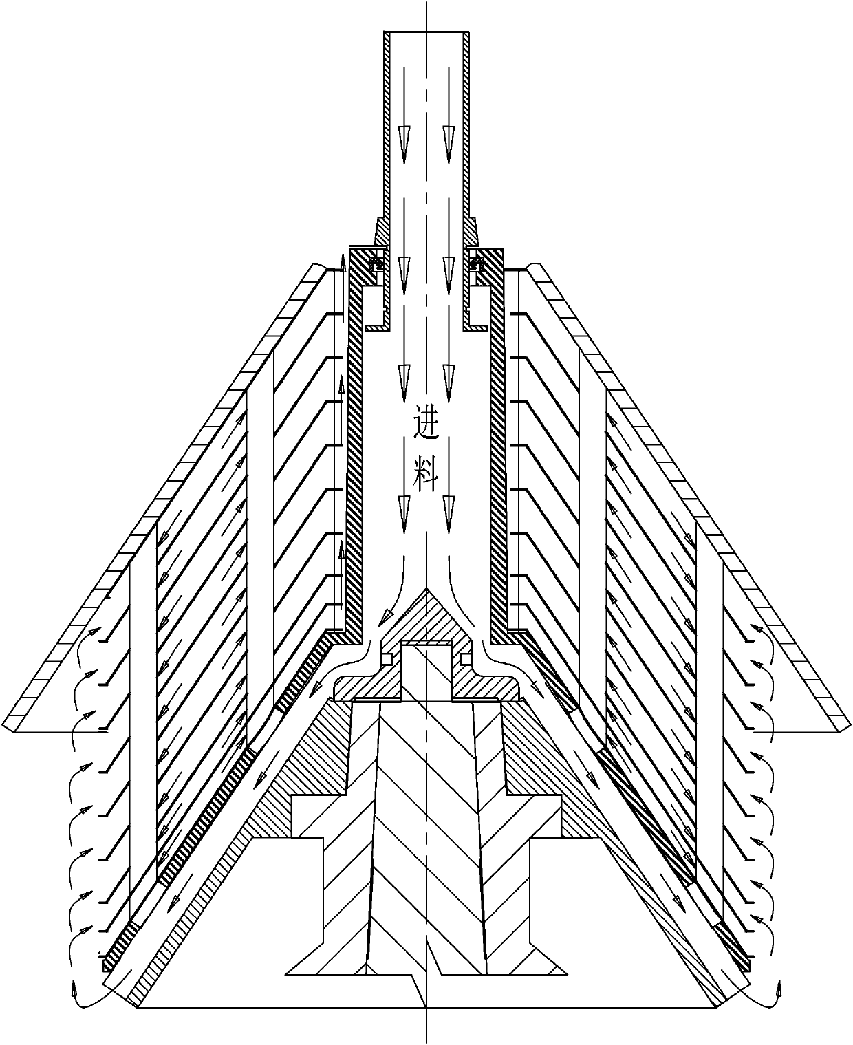
[0048] Such as image 3 , Figure 6 , Figure 7 , Figure 10 , Figure 13 , Figure 14 , Figure 15 , Figure 16 , Figure 17 and Figure 18 As shown, a variable channel structure of a multi-functional disc separator with multiple channels can be changed, including the drum lower body 2, locking screw cover 3, disc bracket base 4, disc bracket 5, disc 6, disc gland 7 and plug 29, the lock screw cover 3 is located at the upper end of the disc bracket base 4, the lock screw cover 3 has an internal thread, and is screwed on the outer surface of the top of the central shaft 1 through the internal thread. On the thread, the locking screw cover 3 is pressed on the disc bracket base 4, the outer peripheral surface of the joint between the drum lower body 2 and the disc bracket base 4 is a conical surface, and the disc bracket base 4 passes through the inner conical hole sleeve Pressed on the outer conical surface of the lower body 2 of the drum, the lower body 2 of the drum ...


PUM


Abstract

The invention relates to a changeable flow channel structure of a multifunctional disc type separator capable of changing multiple flow channels. A locking screw cap is positioned at the upper end ofa disc bracket base, is screwed on the external threads at the top of a center shaft, and is pressed on the disc bracket base; the disc bracket base is pressed on the outer conical surface of the lower body of a rotating drum in a sleeving manner; the lower body of the rotating drum is pressed on the outer conical surface of the top of the central shaft in the sleeving manner; the upper side of the disc bracket base is matched with a disc bracket; a plurality of flow channels are enclosed between the disc bracket base and the disc bracket; a detachable plug is fixed to the lower end of each flow channel; a plurality of layers of discs with gaps therebetween are arranged on the disc bracket in a sleeving manner; the discs are compressed through a disc pressing cap on the uppermost side; thedisc bracket is provided with double rows of lower cone through holes; and each disc is provided with a single row of upper through holes or a single row of lower through holes which communicate withthe lower cone through holes of the disc bracket or is not provided with the through holes. According to the changeable flow channel structure of the multifunctional disc type separator capable of changing the multiple flow channels, a variety of flow channels can be realized.

Description

technical field [0001] The invention belongs to the field of fluid machinery, and relates to a disc separator flow channel, in particular to a convertible channel structure of a multi-functional disc separator capable of changing multiple channels. Background technique [0002] At present, there are many types and models of disc separators, but generally only one type of flow path can be realized, which results in a single function of the disc separator and a narrow range of application, and it is impossible to realize multiple uses of one model. It cannot be realized that one type of machine can realize liquid-liquid two-phase separation and purification, solid-liquid two-phase separation and purification and liquid-liquid-solid three-phase separation at the same time. [0003] In addition, the disc brackets of the current disc separators are generally of integral structure, and the structure of the flow channel in the disc bracket is relatively complicated, which is easy t...

Claims


Application Information

Patent Timeline
Patent Type & Authority Applications(China)
IPC IPC(8): B04B7/00B04B15/00B04B11/00B04B7/08
CPCB04B1/08B04B7/14
Inventor 徐飞刘岩岩李福宝许增金舒德龙
Owner SHENYANG POLYTECHNIC UNIV
Why Eureka
Try Eureka