
Cleaning device for gastroenterology department medical instrument

A technology for medical appliances and cleaning devices, which is applied in the field of medical appliance cleaning, can solve problems such as poor cleaning effect, lower cleaning efficiency of medical appliances, inconvenient insertion and removal of medical appliances, etc., so as to improve the cleaning effect and ensure the cleaning effect Effect

Inactive Publication Date: 2019-06-07
李冉
View PDF7 Cites 5 Cited by
  • Summary
  • Abstract
  • Description
  • Claims
  • Application Information

AI Technical Summary

Problems solved by technology

[0004] But after this cleaning device has cleaned the medical appliance, the surface of the medical appliance will still be adhered to disinfectant water, which will lead to poor cleaning effect, and the cleaning box of the existing cleaning device is a fixed setting, which will lead to putting in and taking out The process of medical utensils is very inconvenient, which reduces the cleaning efficiency of medical utensils

Method used


Image

  • Cleaning device for gastroenterology department medical instrument
  • Cleaning device for gastroenterology department medical instrument
  • Cleaning device for gastroenterology department medical instrument

Examples


Embodiment 1

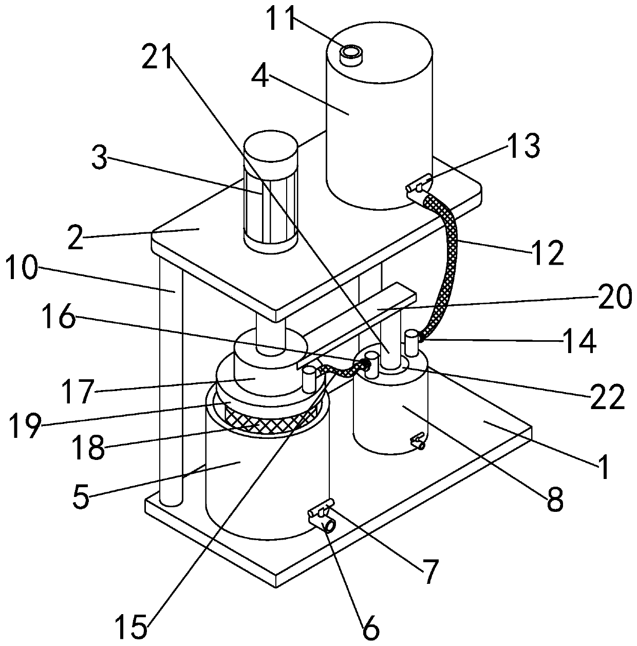
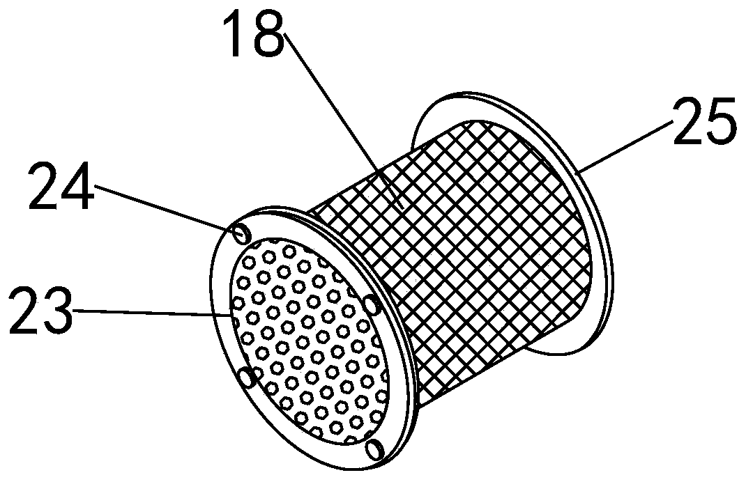
[0033] see figure 1 , in an embodiment of the present invention, a cleaning device for gastroenterology medical appliances includes a cleaning box 5 and a cleaning cage 18, the cleaning box 5 is fixedly installed on a fixed base 1, and one side of the fixed base 1 is symmetrical The column 10 that is vertically arranged is fixedly installed, and the top level fixed mount of column 10 is provided with support top plate 2, and described support top plate 2 is fixedly installed with the electric telescopic cylinder 3 that is used to promote described cleaning net box 18 and stretches into the cleaning box 5 ;

[0034] During use, the medical appliances to be cleaned are placed in the cleaning net cage 18, and the electric telescopic cylinder 3 is used to push the cleaning net cage 18 to move down into the cleaning box 5, and the disinfectant water in the cleaning box 5 is used to clean the net cage 18. The bottom of the cleaning box 5 is provided with a sewage pipe 6, and a sewa...

Embodiment 2

[0041] see Figure 1~5, in an embodiment of the present invention, a cleaning device for gastroenterology medical appliances is different from Embodiment 1 in that it also includes a flushing mechanism linked with the electric telescopic cylinder 3, and the flushing mechanism can clean the medical appliances after preliminary cleaning. Rinse with clean water to remove residual debris and residual disinfectant on the surface to further ensure the cleaning effect of medical appliances.

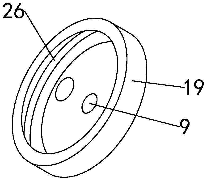
[0042] Specifically, in the embodiment of the present invention, the flushing mechanism includes a water cylinder 8, a water storage tank 4, a piston 26 and a piston rod 21;

[0043] Specifically, a piston 28 is arranged in the water cylinder 8 fixed on the fixed base 1, and the piston rod 21 used to push the piston 28 to move up and down in the water cylinder 8 and the piston rod 21 fixed on one side of the motor base 17 The ends of the support cross bar 20 are fixedly connected. Furthermore, ...


PUM


Abstract

The invention relates to the technical field of medical instrument cleaning, and specifically discloses a cleaning device for a gastroenterology department medical instrument. The cleaning device comprises a cleaning box and a cleaning net cage, and further comprises a flushing mechanism which is linked with the electric telescopic cylinder, wherein an electric telescopic cylinder for pushing thecleaning net cage to extend into the cleaning box is fixedly mounted on a supporting top plate; the bottom end of the telescopic pole on the electric telescopic cylinder is fixedly equipped with a motor base; and a drive motor for driving the cleaning net cage to rotate is fixedly mounted in the motor base. The cleaning device can drive the cleaning net cage to rotate to form eddy current, improves the flushing and cleaning effect of the medical instrument in the cleaning net cage, further can flush the surface of the medical instrument in an upward lifting process to remove residual impurities and residual disinfectant fluid on the surface, and further guarantees the cleaning effect of the medical instrument.

Description

technical field [0001] The invention relates to the technical field of medical appliance cleaning, in particular to a cleaning device for gastroenterology medical appliances. Background technique [0002] In the clinical practice of gastroenterology, due to the repeated use of some medical devices, in order to avoid iatrogenic cross-infection, regular or irregular inactivation of medical devices is required. Traditional disinfection methods mainly include cooking, soaking in disinfectant, ultraviolet rays, and negative oxygen ions. The disinfection effect is not ideal, and there is a risk of cross-infection, which is not conducive to the recovery of patients. [0003] A Chinese invention patent with the publication number CN 109092747 A discloses a cleaning device for medical appliances, which includes a housing, a horizontal baffle is fixedly connected to the bottom of the housing, and a motor bracket is fixedly connected to the left side below the horizontal baffle. A mo...

Claims


Application Information

Patent Timeline
IPC IPC(8): B08B3/06B08B3/02A61B90/70
Inventor 李冉
Owner 李冉
Learn More