
A supercritical carbon dioxide pulse jet oil pipe cleaning device and method

A carbon dioxide, pulse jet technology, applied in cleaning methods and utensils, chemical instruments and methods, cleaning hollow objects, etc., can solve the problems of limited cleaning fluid discharge, frequent replacement of wire brushes, and unsatisfactory cleaning effects. Good application prospects, low energy loss, and the effect of reducing heat dissipation

Active Publication Date: 2018-10-26
WUHAN UNIV
View PDF6 Cites 0 Cited by
  • Summary
  • Abstract
  • Description
  • Claims
  • Application Information

AI Technical Summary

Problems solved by technology

The disadvantages of hot immersion decontamination are high energy consumption and low energy efficiency in an open environment. After adding chemical reagents, the environment is seriously polluted and the working conditions are harsh. The decontamination effect for thicker dirt is not ideal, and the discharge of decontamination liquid is limited; The disadvantages of the intermediate frequency heating mechanical method are large power consumption, high cost, unsatisfactory cleaning effect, and frequent replacement of wire brushes; the main disadvantage of high-pressure water jet cleaning is the cleaning effect on oily dirt with high viscosity or high wax content Not ideal, especially in winter

Method used


Image

  • A supercritical carbon dioxide pulse jet oil pipe cleaning device and method
  • A supercritical carbon dioxide pulse jet oil pipe cleaning device and method

Examples


Embodiment Construction

[0019] Below in conjunction with accompanying drawing, the present invention will be further described through embodiment.

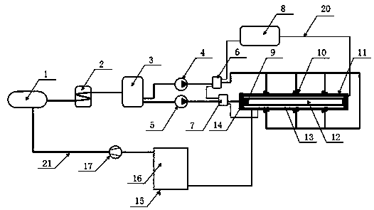
[0020] Such as figure 1 As shown, the main structure of the present invention includes gaseous carbon dioxide storage device 1, refrigeration device 2, liquid carbon dioxide storage device 3, high-pressure pump one 4, high-pressure pump two 5, supercritical carbon dioxide storage device one 6, supercritical carbon dioxide storage device two 7 , heating device 8, center self-excited oscillation pulse nozzle 9, side self-excited oscillation pulse nozzle 10, cleaning chamber 11, oil pipe 12, cleaning chamber end cover 14, crude oil discharge port 15, oil-gas separation device 16, carbon dioxide gas compression device 17, and hot water pipeline 20 and carbon dioxide pipeline 21.

[0021] The right end of the gaseous carbon dioxide storage device 1 is connected to the refrigeration device 2 through a pipeline, and the lower part is connected to the outlet of...


PUM


Abstract

The invention discloses a fouling cleaning device and method for a supercritical carbon dioxide pulse jet flow oil pipe. Supercritical carbon dioxide pulse jet flow is adopted for cleaning fouling of the inner wall and the outer wall of the oil pipe. First, gasified carbon dioxide is charged into a storage device and cooled through a refrigerating device to be liquefied and stored in a storage tank, the liquefied carbon dioxide in the storage tank is heated through a heating device to be supercritical carbon dioxide after being pressurized through a high-pressure pump, and then high-speed supercritical carbon dioxide pulse jet flow with pulse frequency being 30-80 Hz is formed through self-oscillation pulse spray nozzles on the end cover and the inner wall of a fouling cleaning chamber and used for carrying out pulse flushing on the inner wall and the outer wall of the oil pipe; the fouling on the walls of the pipe is easy to clean after being dissolved with the supercritical carbon dioxide and being subjected to pulse flushing with the pulse jet flow in a combined mode; after fouling cleaning, the supercritical carbon dioxide is subjected to pressure reduction through a separator and converted into gasified carbon dioxide to be separated from the fouling, and fouling cleaning is completed; the gasified carbon dioxide is reused, and the fouling is recycled. The device and method save energy, are environmentally friendly, safe and efficient, and the fouling is easy to separate and recycle.

Description

technical field [0001] The invention belongs to the field of oil pipe cleaning equipment and technology in oil and gas engineering, and relates to a supercritical carbon dioxide pulse jet oil pipe cleaning device and method. Background technique [0002] In the oil and gas industry, tubing is a very common downhole tool, and its usage is large, which directly affects the cost of oil production. After the tubing has been working for a certain period of time, oil, wax and other impurities will adhere to the inner and outer walls, which will reduce the production efficiency of the oil well, or even stop production, requiring workover to clean and repair the tubing. In order to avoid downhole accidents, the oil pipe must be lifted out of the oil well before cleaning. How to improve the effect and efficiency of oil pipe cleaning and reduce the cost of cleaning, technicians have been working hard to explore better technology. [0003] At present, the commonly used oil pipe clean...

Claims


Application Information

Patent Timeline
Patent Type & Authority Patents(China)
IPC IPC(8): B08B7/00B08B9/023B08B9/027
CPCB08B7/0021B08B9/023B08B9/027
Inventor 康勇黄满王晓川胡毅蔡灿李登
Owner WUHAN UNIV
Learn More