Material additive manufacturing device and method of high-degree-of-freedom complex structural part

A complex structure, additive manufacturing technology, applied in the field of additive manufacturing, can solve the problems of reducing forming efficiency, increasing powder consumption, twisting deformation, etc., to achieve the effect of improving forming efficiency, avoiding rebound deformation, and reducing processing costs

Active Publication Date: 2019-06-07
HUAZHONG UNIV OF SCI & TECH
View PDF9 Cites 13 Cited by
  • Summary
  • Abstract
  • Description
  • Claims
  • Application Information

AI Technical Summary

Problems solved by technology

[0006] At present, there are still some problems in processing high-degree-of-freedom complex structural parts with this technology. Distortion, cracking or forming failures occur from time to time. Therefore, it is necessary to add some auxiliary support structures at the same time to ensure the smooth forming of parts.
[0007] Currently commonly used support forms, such as the lower tree support, lower grid support and lower solid support described in the patent application with the publication number CN107685148A, mostly grow vertically or obliquely from the substrate; when the parts to be processed When the suspended part of the suspension is separated from the base plate, the lower tree-shaped support and the lower grid support structure will form a thin and tall structure. Under the influence of thermal stress and the friction of the powder spreading device, this kind of thin and tall structure is insufficient in strength and rigidity. The high support structure is easy to break and difficult to form; although the solid support can achieve a better support effect, it can only be removed by machining, which also increases the powder consumption and reduces the forming efficiency

Method used


Image

  • Material additive manufacturing device and method of high-degree-of-freedom complex structural part
  • Material additive manufacturing device and method of high-degree-of-freedom complex structural part
  • Material additive manufacturing device and method of high-degree-of-freedom complex structural part

Examples


Embodiment 1

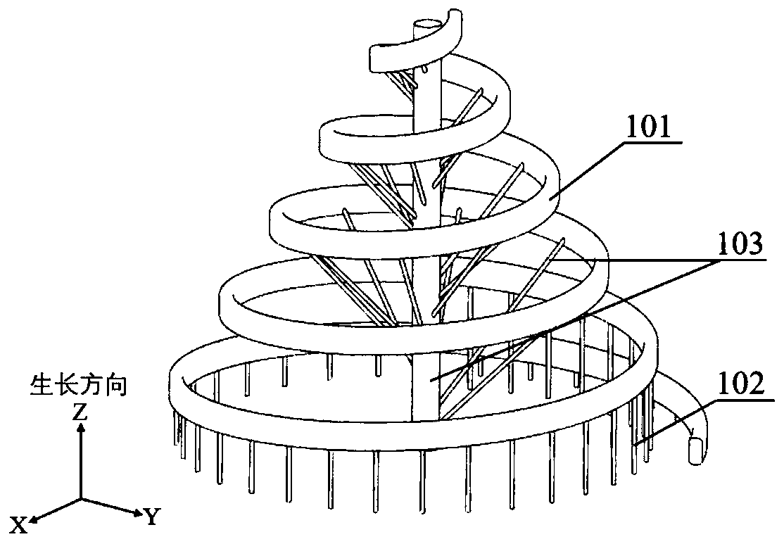
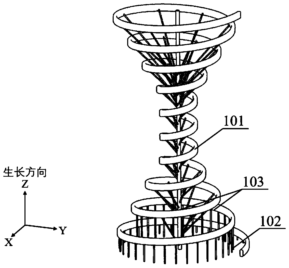
[0052] This embodiment 1 is to explain the three-dimensional spatial positioning conformal tree-shaped support structure used for additive manufacturing of high-degree-of-freedom and complex-structure 60Mn steel parts, and the structural shape of the 60Mn steel parts is similar to a cone-shaped spring.

[0053] Include the following steps:

[0054] Step 1: Design and optimize the 60Mn steel part structure 101, and generate a corresponding three-dimensional solid model;

[0055] Step 2: Determine the placement form and position of the three-dimensional solid model of the 60Mn steel part structure 101, the axis of the 60Mn steel part structure 101 is parallel to the growth direction;

[0056] Step 3: for the structure and shape of the 60Mn steel part structure 101, select the three-dimensional space positioning follow-the-shaped tree-shaped support structure, add a small amount of conventional support structures 102 and the three-dimensional space positioning follow-the-shaped t...

Embodiment 2

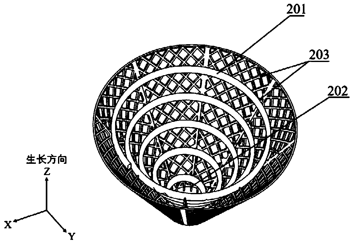
[0060] This embodiment 2 is to explain the three-dimensional space positioning conformal grid support structure used for additive manufacturing of high-degree-of-freedom and complex-structure 304 stainless steel parts. The structure of 304 stainless steel parts is similar to an inverted cone spring.

[0061] Include the following steps:

[0062] Step 1: Design and optimize the 304 stainless steel part structure 201, and generate a corresponding three-dimensional solid model;

[0063] Step 2: Determine the placement form and position of the three-dimensional solid model of the 304 stainless steel part structure 201, the axis of the 304 stainless steel part structure 201 is parallel to the growth direction;

[0064] Step 3: For the structure and shape of the 304 stainless steel part structure 201, select the three-dimensional space positioning conformal grid support structure, add a small amount of conventional support structure 202 and three-dimensional space positioning grid s...

Embodiment 3

[0068] This embodiment 3 is to explain the three-dimensional spatial positioning conformal truss support structure used for additive manufacturing of high-degree-of-freedom and complex-structure NiTi alloy parts. structure has the broadest applicability.

[0069] Include the following steps:

[0070] Step 1: Design and optimize the NiTi alloy part structure 301, and generate a corresponding three-dimensional solid model;

[0071] Step 2: Determine the placement position of the three-dimensional solid model of the NiTi alloy part structure 301. Any placement form can be selected to ensure a lower processing height as much as possible, so as to reduce the time required for powder spreading and improve processing efficiency;

[0072] Step 3: Select the three-dimensional space positioning conformal truss support structure, according to the structure and shape of the NiTi alloy part structure 301, construct a three-dimensional space positioning conformal truss support structure 30...


PUM


Abstract

The invention belongs to the field of material additive manufacturing and provides a material additive manufacturing auxiliary method and device. The method comprises the steps of designing and optimizing the structure of a part to generate a corresponding three-dimensional entity model; establishing an appropriate three-dimensional special orientation supporting structure according to the part structure and shape of the part; machining raw material powder layer by layer to form a compact entity according to set machining parameters with the part and the three-dimensional spatial orientation supporting structure as objects to be machined and obtaining a combination composed of the three-dimensional spatial orientation supporting structure and the part; and removing the three-dimensional spatial orientation supporting structure on the combination to obtain the part. The invention further provides the three-dimensional spatial orientation supporting structure with the extensive applicability. Through the novel method and device provided for manufacturing the high-degree-of-freedom complex structural part at low cost, high efficiency and high quality, traditional material and processlimitation is broken through, and existing technical problems are solved.

Description

technical field [0001] The invention belongs to the field of additive manufacturing, and specifically relates to an additive manufacturing device and method for high-degree-of-freedom complex structural parts. It has a wide range of applications, especially for SMA (the full English name is Shape Memory Alloy, referred to as SMA). Background technique [0002] The essence of part manufacturing is actually to accurately transfer the designed geometric dimensions to the physical workpiece through the forming equipment. With the development of science and technology, precision manufacturing fields such as aerospace and automobiles have put forward higher requirements for the structural shape, dimensional accuracy, forming quality and efficiency of parts. [0003] Parts with simple structural shapes are easy to form, have stable performance, and the manufacturing process has become increasingly mature. However, due to their simple structure and low degree of freedom, the practi...

Claims


Application Information

Patent Timeline
Patent Type & Authority Applications(China)
IPC IPC(8): B22F3/00B33Y10/00B33Y30/00B22F10/43B22F12/00
CPCY02P10/25
Inventor 王泽敏赵春阳喻寒琛梁海龙杨晶晶曾晓雁
Owner HUAZHONG UNIV OF SCI & TECH
Why Eureka
Try Eureka