Horizontal plate shearing machine capable of automatically adjusting shearing angle and shearing angle adjusting control method for horizontal plate shearing machine

A shearing angle, automatic adjustment technology, applied in the direction of shearing device, the accessory device of the shearing machine, the tool used in the shearing machine, etc., can solve the problem of affecting the cutting quality, the service life of the blade, the quality of the shearing workpiece, and the Problems such as shearing effect, to achieve the effect of coordinated and reliable equipment operation, simple structure, and accurate shearing processing

Pending Publication Date: 2019-06-07
ANHUI DONGHAI MACHINE MFG CO LTD
View PDF1 Cites 5 Cited by
  • Summary
  • Abstract
  • Description
  • Claims
  • Application Information

AI Technical Summary

Problems solved by technology

If the shearing angle increases or decreases, the magnitude of the shearing force on both sides will be different, which will affect the shearing effect, and will also change the knife-edge gap at the joint between the shearing surfaces of the two moving knives, and the accuracy of the knife-edge gap The requirements are high, and the gap between the blades is too large, which will affect the quality of the cu

Method used


Image

  • Horizontal plate shearing machine capable of automatically adjusting shearing angle and shearing angle adjusting control method for horizontal plate shearing machine
  • Horizontal plate shearing machine capable of automatically adjusting shearing angle and shearing angle adjusting control method for horizontal plate shearing machine

Examples


Embodiment 1

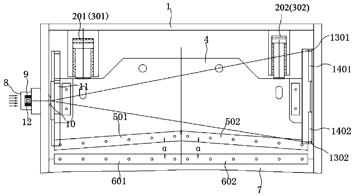
[0034] Such as figure 1As shown, a horizontal plate shearing machine with automatic adjustment of shearing angle in this embodiment comprises a frame 1, and said frame 1 is provided with a knife rest 4 and a workbench 7 distributed along the horizontal direction, and the workbench 7 Static knives (left static knife 601 and right static knife 602) are arranged on the top, and moving knives (left moving knife 501 and right moving knife 502) cooperating with the static knives are provided on the knife rest 4, and the left side of the frame 1 is provided with There are side fulcrums 8, and the side fulcrums 8 are connected to the rollers 10 through disc springs 9. The left side of the knife rest 4 is correspondingly provided with a guide rail plate 11, and the right side of the knife rest 4 is located on the inner wall of the frame 1 and a first sticker is installed. The first inductor 12 , the second inductor 1301 and the third inductor 1302 are mounted on the plywood 1401 and th...

Embodiment 2

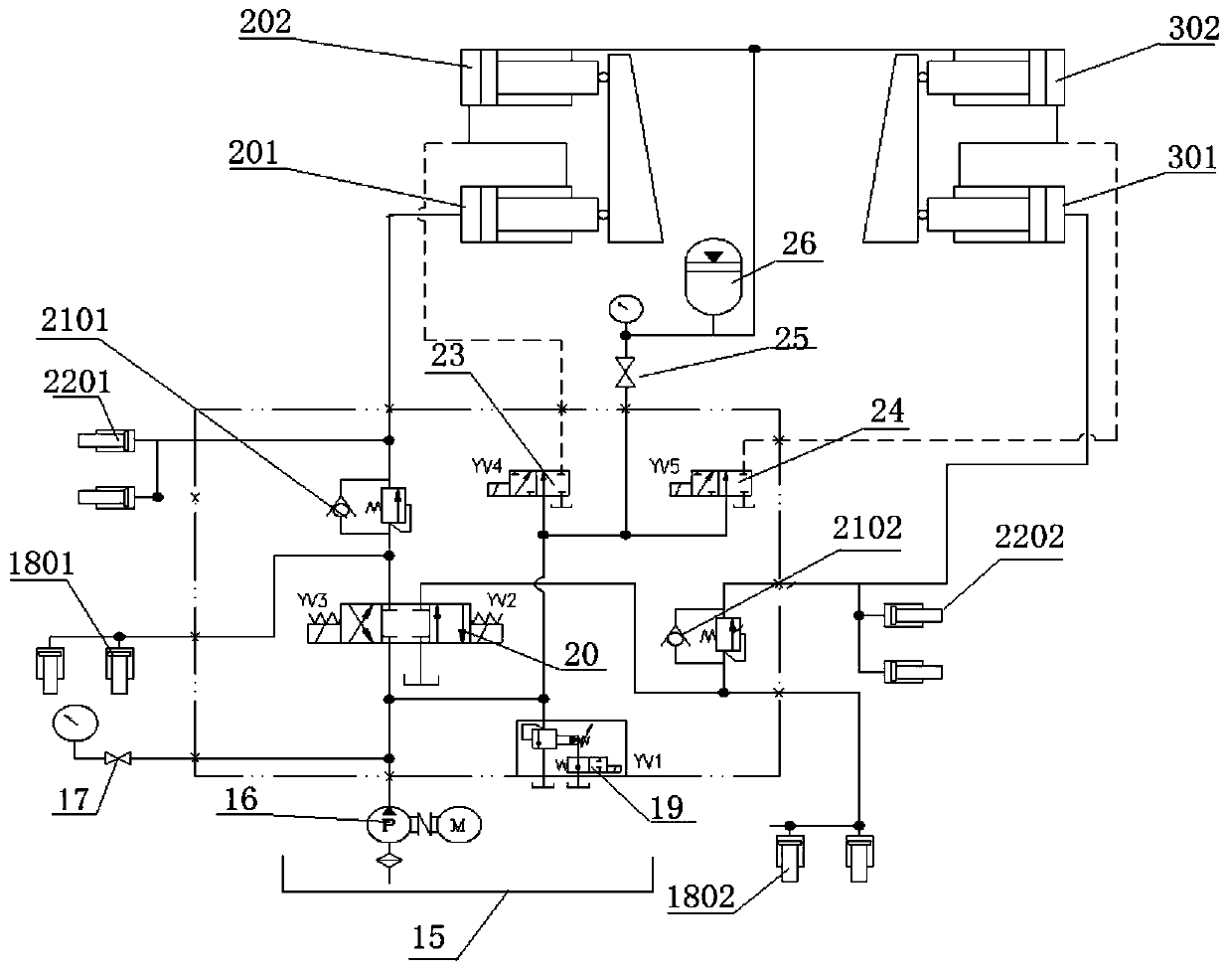
[0039] A horizontal plate shearing machine with automatic adjustment of shearing angle in this embodiment, its structure is basically the same as in Embodiment 1, the main difference is that in this embodiment, the two ends of the knife rest 4 are connected to the main oil cylinder and the auxiliary oil cylinder respectively, Specifically, in this embodiment, two groups of knife rests 4 and movable knife sets are arranged symmetrically on both sides of the workbench 7, wherein the two ends of the left knife rest 4 are respectively connected with the left master cylinder 201 and the left auxiliary cylinder 202, The two ends of the right tool rest 4 are respectively connected with the right master cylinder 301 and the right auxiliary cylinder 302, figure 1 Only one tool holder is shown in .

[0040] combine figure 2 , the hydraulic system of the shearing machine includes an oil tank 15, an oil pump 16 and an electro-hydraulic reversing valve 20, wherein the oil inlet of the oi...

Embodiment 3

[0043] A horizontal plate shearing machine with automatic adjustment of shearing angle in this embodiment has the same structure as in Embodiment 2. The specific process of the shearing angle adjustment control method in this embodiment is: placing the workpiece to be sheared on the workbench On the static knife, push the roller 10 to the right through the side fulcrum 8, so that the tool rest 4 fits the first fitting plate 1401 and the second fitting plate 1402 on the inner wall of the right side of the tool rest to the right, and passes through the left oil cylinder 2 and the right The oil cylinder 3 drives the knife rest 4 to carry out horizontal cutting movement along the laminated board, and detects whether the knife rest 4 is in a horizontal state during the cutting process (by the second sensor 1301 and the third sensor 1302 sensing and measuring the distance between the first sensor 12 and the first sensor 12). The distance is used to detect whether the tool holder is i...


PUM


Abstract

The invention discloses a horizontal plate shearing machine capable of automatically adjusting a shearing angle and a shearing angle adjusting control method for the horizontal plate shearing machineand belongs to the technical field of forging machine tools. The horizontal plate shearing machine capable of automatically adjusting the shearing angle comprises a rack, a knife rest and a workbench;the rack is internally provided with the knife rest and the workbench which are distributed in a horizontal direction; the workbench is provided with a static knife; the knife rest is provided with amoving knife matched with the static knife; the left side of the rack is provided with a side supporting point; the side supporting point is connected with a rolling wheel through a disc spring; theleft side of the knife rest is correspondingly provided with a guide rail plate; the position, on the inner wall of the rack, of the right side of the knife rest is provided with a first laminating plate and a second laminating plate; and the side supporting point, the first laminating plate and the second laminating plate are provided with a first inductor, a second inductor and a third inductorrespectively. According to the technical scheme of the invention, the shearing angle of the horizontal plate shearing machine can be automatically adjusted, so that the shearing angle is ensured to befixed.

Description

technical field [0001] The invention belongs to the technical field of shearing machines, and more specifically relates to a horizontal shearing machine with automatic adjustment of shearing angle and a control method for adjusting the shearing angle. Background technique [0002] Shearing machine is a kind of forging machinery. It is a kind of equipment with wide application. It is mainly used in the metal processing industry. It fixes the steel plate through the pressing frame of the shearing machine and uses the relative movement between the upper and lower blades. , apply shear force to metal sheets of various thicknesses, so that the sheets are broken and separated according to the required size. The shearing machine processing products are widely used in aviation, light industry, metallurgy, chemical industry, construction, shipbuilding, automobile, electric power, electrical appliances, decoration and other industries to provide the required special machinery and comp...

Claims


Application Information

Patent Timeline
IPC IPC(8): B23D15/08B23D33/02B23D35/00
Inventor 石贤锋石贤林郑盼盼陶树仁
Owner ANHUI DONGHAI MACHINE MFG CO LTD
Why Eureka
Try Eureka