
A kind of preparation method of active cooling structure

An active cooling and inner cylinder technology, applied in the field of precision machining, can solve the problems that the geometric dimension accuracy of the inner cooling channel cannot be guaranteed, reduce the processing efficiency of the overall structural components, and increase the processing cost, etc., so as to achieve reliable overall structural performance and ensure geometric shape Consistency, the effect of reducing processing costs

Active Publication Date: 2022-05-31
XIAN YUANHANG VACUUM BRAZING TECH
View PDF10 Cites 0 Cited by
  • Summary
  • Abstract
  • Description
  • Claims
  • Application Information

AI Technical Summary

Problems solved by technology

The above method has the following disadvantages: 1) Since the internal cooling channels need to be milled one by one on the machine tool, it takes a long time, and the next process can only be carried out after all the cooling channels are milled, which greatly reduces the overall structural components. 2) When the shape of the cooling channel is complex, the milling process is also difficult, and the geometric dimension accuracy of the internal cooling channel cannot be guaranteed; 3) When the size of the active cooling structure is large When the value is large, there will be a large deformation in the machining inner cooling channel

Method used


Image

  • A kind of preparation method of active cooling structure
  • A kind of preparation method of active cooling structure
  • A kind of preparation method of active cooling structure

Examples


preparation example Construction

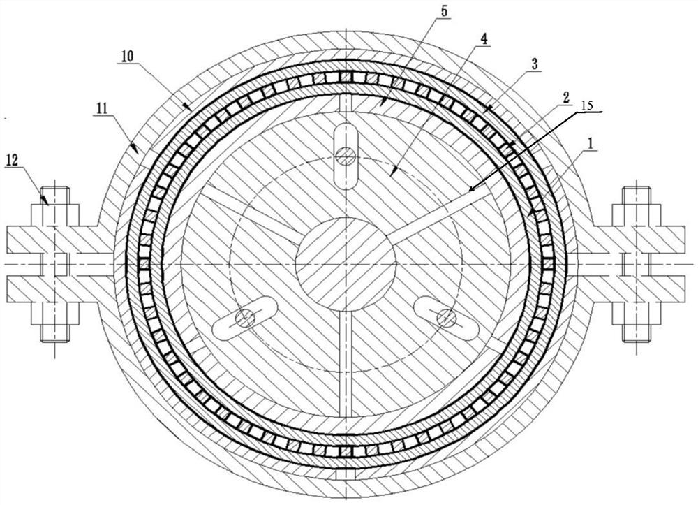
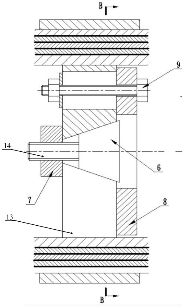
are respectively fixedly connected with the inner support bottom plate 8 through the bottom plate fixing member 9;

Described shell tooling 11 comprises two symmetrically arranged hoops, and both ends of the hoops are respectively provided with matching clamps

12; The hoop clamps the clamps 12 at both ends of the hoop after the outer cylinder is clamped, respectively.

Concretely, described inner support 4 comprises three arc-shaped support blocks 13 enclosing cylindrical supports, arc-shaped support blocks

13 is set in a centrosymmetric manner.

The described adjuster 6 is close to the adjustment hole, and the adjuster 6 adjusts its position in the adjustment hole by the rotation of the fastening bolt 14.

The position of the adjuster 6 changes to adjust the size of the adjustment gap 15 between the arc-shaped support blocks 13.

Further, described paste solder Ni-Li base solder Ni-Li-Gr14B3Si4.5, and contain mass fraction

0.01-0.08% C, the solder melted under capillary ...

Embodiment 1

[0071] 10) Carry out a pressure performance test on the fabricated active cooling structure.

Embodiment 2

[0088] Heating to 700°C at a rate of 180°C / h for 20min;

[0089] Heating to 900°C at a rate of 360°C / h for 120min;

[0090] Heating to 1020°C at a rate of 500°C / h, brazing at 1020°C ± 5°C, and holding for 30min;

[0091] The cooling procedure after brazing is: cooling to 700°C at a rate of 240°C / h, followed by vacuum cooling in the furnace to 200°C for filling

[0094] 10) Carry out a pressure performance test on the fabricated active cooling structure.


PUM

PropertyMeasurementUnit
thicknessaaaaaaaaaa

Abstract

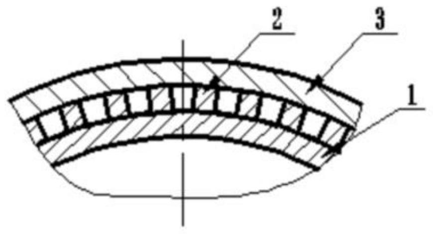
The invention discloses a method for preparing an active cooling structure, which includes the following operations: 1) rolling a stainless steel substrate into an inner cylinder as a high-temperature gas flow channel; 2) using laser, high-pressure water or wire cutting to make stainless steel ribs; 3) ) roll the alloy cover plate into an outer cylinder that matches the inner cylinder, and then cut the outer cylinder into several pieces along the axial direction; 4) place the inner support in the inner cylinder, and place the prepared ribs 5) Apply paste-like solder on the bottom of one side of the rib, and then fix the amorphous foil-like solder on the inner surface of the outer tube corresponding to the rib; 6) Vacuum brazing at 900°C-1020°C. The cooling channel ribs adopted in the present invention are first cut in batches and then integrally vacuum brazed, which can greatly reduce the processing time of the cooling channel in the active cooling structure, improve the processing efficiency of the overall components, and reduce the processing cost.

Description

A kind of preparation method of active cooling structure technical field [0001] The invention belongs to the technical field of precision machining, and relates to a preparation method of an active cooling structure. Background technique [0002] The hot-end components of the super engine often have to withstand severe high temperature (2300 ° C), high pressure (20 MPa) operating conditions, It is generally necessary to design an active cooling structure to achieve the cooling effect. Existing active cooling structures are generally made of superalloy outside The skin is constructed with a stainless steel housing with internal cooling channels. The method of processing this active cooling structure at present is mainly: firstly mill the surface of the inner shell to produce a cooling strip with ribs [0003] The cooling groove is then connected with the outer skin to form a cooling structure. The above method has the following disadvantages: 1) Since the inner cooling ...

Claims


Application Information

Patent Timeline
Patent Type & Authority Patents(China)
IPC IPC(8): B23P15/00
Inventor 任耀文李文昌李淑芳任军任轩
Owner XIAN YUANHANG VACUUM BRAZING TECH
Learn More