Wrist rotating clamp structure for hydraulic manipulator

A manipulator and rotary clamp technology, applied in the field of manipulators, can solve the problems of restricting the long-term development of hydraulic manipulators, complex motor structure, insufficient input power, etc., and achieve the effect of easy refinement, simple structure, and simplified structure.

Pending Publication Date: 2019-06-07
HANGZHOU YUKONG MECHANICAL & ELECTRICAL ENG
View PDF7 Cites 8 Cited by
  • Summary
  • Abstract
  • Description
  • Claims
  • Application Information

AI Technical Summary

Problems solved by technology

These requirements result in motors that are complex, costly, heavy, and poorly maintainable
It is difficult for the existing motors on the market to meet the requirements of the hydraulic manipulator for the wrist rotation function. If self-development is bound to be limited by factors such as materials, processing capabilities, and small market demand, it will lead to insufficient motivation for enterprise R&D investment and high costs. , with little effect, seriously restricting the rapid development and wider application of hydraulic manipulators

Method used


Image

  • Wrist rotating clamp structure for hydraulic manipulator
  • Wrist rotating clamp structure for hydraulic manipulator
  • Wrist rotating clamp structure for hydraulic manipulator

Examples


Embodiment Construction

[0039] The following examples can make those skilled in the technical field understand the present invention more comprehensively, but do not limit the present invention in any way.

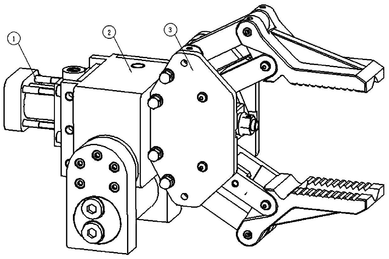
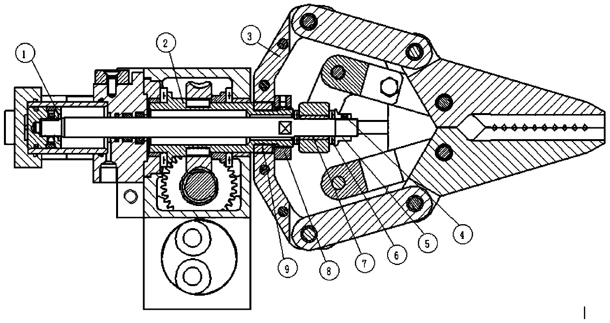
[0040] The wrist clamp structure for the hydraulic manipulator provided by the present invention includes three parts: a linear oil cylinder 1 , a speed reduction mechanism 2 and a gripper 3 . Among them: the deceleration mechanism 2 is used to realize the amplification of the torque of the micro hydraulic motor 2-1 and the reduction of the rotational speed, and further realize the low-speed and high-torque rotation of the gripper 3; the linear oil cylinder 1 drives the parallel opening and closing of the gripper 3 through a parallelogram mechanism to realize Grab and release of objects.

[0041] figure 1 It is an isometric drawing of the actual implementation of the structure of the hydraulic mechanical wrist tong, showing the spatial positional relationship among the linear cylinder 1, the reduc...


PUM


Abstract

The invention relates to a manipulator technology, and provides a wrist rotating clamp structure for a hydraulic manipulator. The structure comprises a linear oil cylinder, a micro hydraulic motor, aspeed reducing mechanism and a pawl; the linear oil cylinder is arranged by adopting a rear mode; the micro hydraulic motor and the speed reducing mechanism are positioned between the linear oil cylinder and the pawl; an output shaft of the micro hydraulic motor is connected to the speed reducing mechanism, and is vertically staggered with a piston rod of the linear oil cylinder; a worm wheel output shaft of the speed reducing mechanism is of a hollow structure; the piston rod of the linear oil cylinder is connected to a driving mechanism of the pawl after penetrating through the worm wheel output shaft, and drives opening or closing thereof; and the micro hydraulic motor drives the pawl to realize forward-reverse rotation through the speed reducing mechanism. The structure is simple in structure, low in technical difficulty, high in reliability, excellent in maintainability and economy, easy to realize, high in speed reducing ratio, high in wrist rotating torque and low in lowest stable rotating speed, allows staggered arrangement of the hydraulic motor and the pawl to achieve more compact and flexible structure, and has self-locking characteristics on a worm wheel and a worm rod.

Description

technical field [0001] The invention relates to manipulator technology, in particular to a wrist-rotating clamp structure for a hydraulic manipulator. Background technique [0002] The hydraulic manipulator is a mechanical arm driven by hydraulic pressure. Its biggest feature is its large load / weight ratio. It is suitable for occasions that are sensitive to loads and require strong holding capacity. Its own sealing structure is convenient for underwater applications. Underwater, the hydraulic manipulator is the standard equipment for submersibles and underwater robots, which can complete underwater sampling, picking, deployment and other operations; remote work. [0003] The wrist tong joint of the manipulator is the most integrated core structure of the manipulator, and it is also the bottleneck of the development of manipulator technology. It requires the two functions of 360-degree forward and reverse continuous rotation of the wrist and opening and closing of the gripp...

Claims


Application Information

Patent Timeline
Patent Type & Authority Applications(China)
IPC IPC(8): B25J15/02B25J9/10
Inventor 刘松顾临怡吴新然杜晓敏巩陈刚
Owner HANGZHOU YUKONG MECHANICAL & ELECTRICAL ENG
Why Eureka
Try Eureka