Efficient LNG conveying pump impeller

A transfer pump, high-efficiency technology, applied in the field of high-efficiency LNG transfer pump impeller, can solve problems such as cavitation, high production cost, bubble burst, etc., achieve the effect of increasing the flow area of ​​the inlet, simple processing, and avoiding clogging

Inactive Publication Date: 2019-06-07
苏州横海流体动力科技有限公司
View PDF5 Cites 3 Cited by
  • Summary
  • Abstract
  • Description
  • Claims
  • Application Information

AI Technical Summary

Problems solved by technology

The impeller is an important part of the LNG pump. In order to avoid blockage of the impeller inlet and ensure the number of blades to prevent eddy currents in the impeller channel, the traditional method is to use a combination of long and short blades. This method requires high processing. Difficult to make, high production cost, and the dynamic balance of the impeller is not easy to control, the water loss of the fluid on the impeller is relatively large, which will reduce the efficiency of the pump
At the sa

Method used


Image

  • Efficient LNG conveying pump impeller
  • Efficient LNG conveying pump impeller
  • Efficient LNG conveying pump impeller

Examples


Embodiment Construction

[0025] The present invention will be described in further detail below in conjunction with the accompanying drawings.

[0026] Figure 1-7 A high-efficiency LNG delivery pump impeller of the present invention is schematically given.

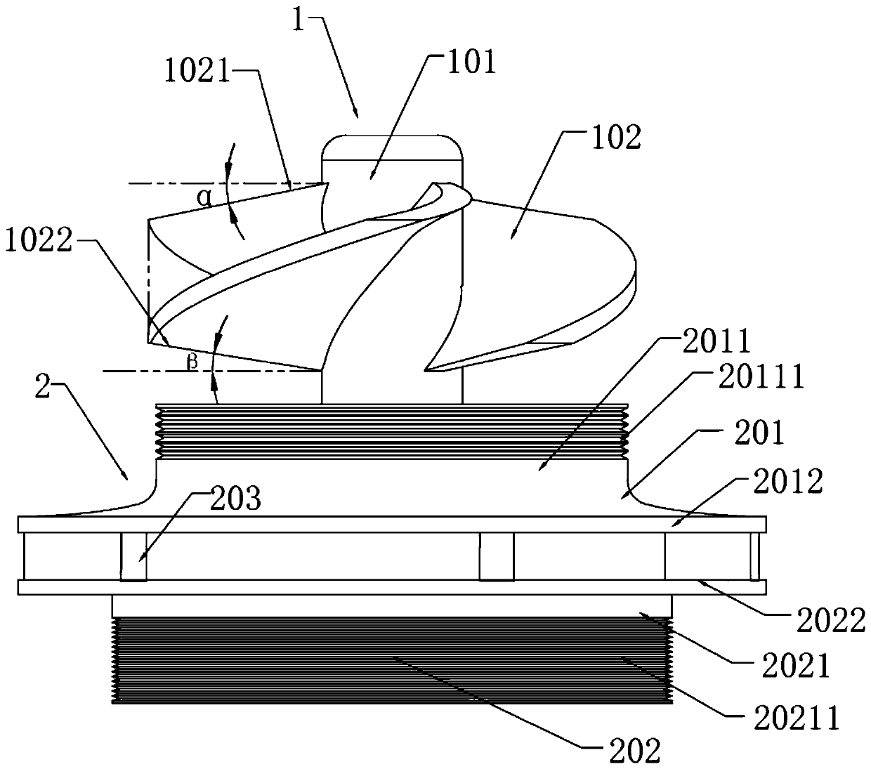
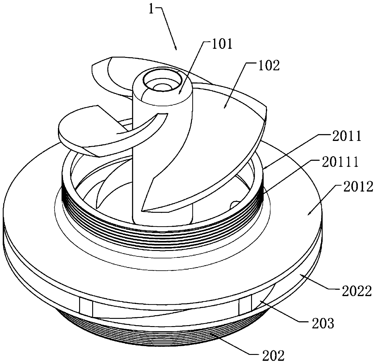
[0027] like Figure 1-Figure 4 As shown, a high-efficiency LNG transfer pump impeller is provided, which includes a drainage part 1 and a pressurized part 2 connected to the drainage part 1. The drainage part 1 includes a first hub 101 and a plurality of helical first blades 102, and a plurality of first blades 102 are evenly distributed on the first hub 101, the first blade 102 is connected to the first hub 101 through the connection surface 1024, and the two ends of the connection surface 1024 are respectively extended away from the first hub 101 to form the first end surface of the first blade 102 1021 and the second end surface 1022, the outer edge 1023 of the first blade 102 is formed between the first end surface 1021 and the outer end of...


PUM


Abstract

The invention discloses an efficient LNG conveying pump impeller. The efficient LNG conveying pump impeller comprises a flow guide part, and a pressurizing part which is connected to the flow guide part, wherein the flow guide part comprises a first hub, and a plurality of first spiral blades which are uniformly distributed on the first hub; the first blades are connected to the first hub throughfirst connecting surfaces; the pressurizing part comprises a first cover plate assembly, a second cover plate assembly, and a second hub which is formed on the second cover plate assembly; second blades are uniformly distributed in the circumference a spiral flowing channel is formed between every two adjacent second blades; and the second hub is connected to the first hub. With the adoption of the efficient LNG conveying pump impeller, the inlet flowing area is effectively increased, so that an inlet is effectively prevented from blockage, and eddy current is effectively prevented from generating in a turbine flowing channel; the flow guide part and the pressurizing part are designed, so that the whole conveying pump impeller has the beneficial effects of being low in gas etching, high inefficiency, and simple to process.

Description

technical field [0001] The invention relates to the technical field of fluid machinery, in particular to an impeller of a high-efficiency LNG delivery pump. Background technique [0002] The present invention requires that the blade inlet m is 0, t is -0.2-0.4; the blade outlet m is 0.56-0.73, and t is 2.3. This is used to determine the shape of the booster impeller. The share of natural gas in energy consumption has steadily increased in recent years. The transportation and storage of natural gas are basically converted into LNG (liquefied natural gas). LNG pump is an important equipment of LNG filling station, mainly used for pressurization and unloading work. The impeller is an important part of the LNG pump. In order to avoid blockage of the impeller inlet and ensure the number of blades to prevent eddy currents in the impeller channel, the traditional method is to use a combination of long and short blades. This method requires high processing. The manufacture is di...

Claims


Application Information

Patent Timeline
IPC IPC(8): F04D29/22F04D29/24F04D29/66
Inventor 齐海涛赵松岭
Owner 苏州横海流体动力科技有限公司
Why Eureka
Try Eureka