Heat sink based on chimney effect

A technology of chimney effect and heat sink, which is applied in semiconductor devices of light-emitting elements, cooling/heating devices of lighting devices, lighting and heating equipment, etc., which can solve the problem of inability to achieve fast and effective heat dissipation, smooth air flow, and unfavorable small size and light weight problems such as the development of modernization, to achieve the effect of increasing air flow speed, improving reliability and speeding up air flow

Pending Publication Date: 2019-06-07
INST OF ENGINEERING THERMOPHYSICS - CHINESE ACAD OF SCI
View PDF0 Cites 0 Cited by
  • Summary
  • Abstract
  • Description
  • Claims
  • Application Information

AI Technical Summary

Problems solved by technology

This will lead to an increase in the weight of the radiator, which is not conducive to the development of small and light
In addition, as the size and number of heat sinks increase, the heat sinks will become denser, which cannot ensure smooth air flow, and cannot achieve rapid and effective heat dissipation.

Method used


Image

  • Heat sink based on chimney effect
  • Heat sink based on chimney effect
  • Heat sink based on chimney effect

Examples


no. 1 example

[0050] In a first exemplary embodiment of the present disclosure, a chimney effect based radiator is provided.

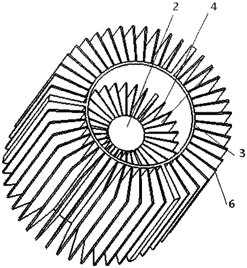
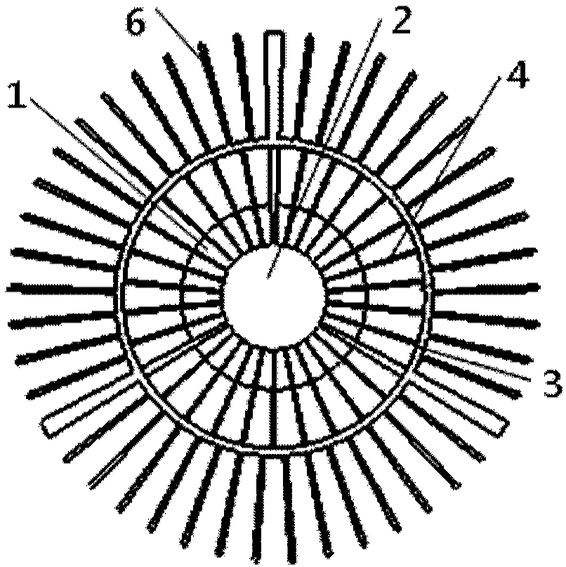
[0051] figure 1 It is a structural schematic diagram of a chimney effect-based radiator according to the first embodiment of the present disclosure. figure 2 for figure 1 A top view of a chimney-effect based radiator is shown. Such as figure 1 with figure 2As shown, this embodiment is a radiator based on the chimney effect comprising a layer of thin-walled cylindrical structure. It specifically includes a heat source mounting substrate 1; a heat conducting column 2, the first end of which is connected to the heat source mounting substrate 1; a first thin-walled cylinder 3, which is nested outside the heat conducting column 2; N1 first-layer heat sinks 4, It is radially arranged between the heat conduction column 2 and the first thin-walled cylinder 3; the extension surface of the plane where each first layer of heat sink 4 is located passes through the centra...

no. 2 example

[0053] In a second exemplary embodiment of the present disclosure, a chimney effect based radiator is provided. Compared with the first embodiment, this embodiment differs in that a second thin-walled cylinder 5 is added on the basis of the first embodiment.

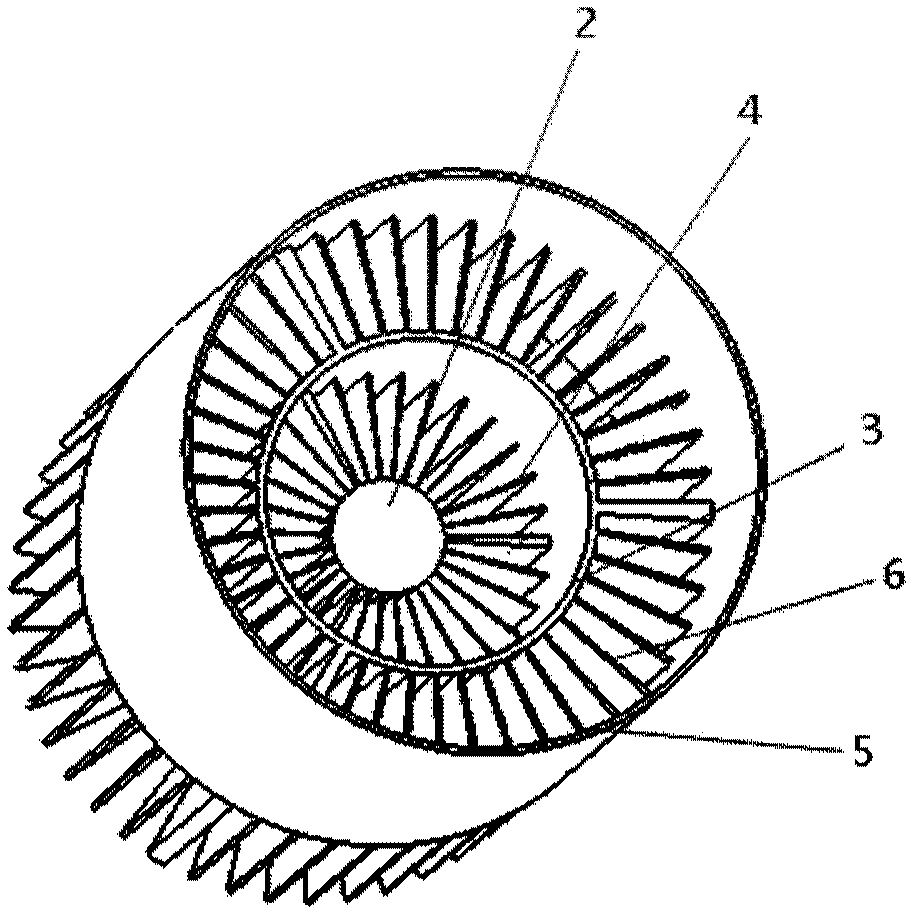
[0054] image 3 It is a schematic structural diagram of a radiator based on the chimney effect according to the second embodiment of the present disclosure. Figure 4 for image 3 A top view of a chimney-effect based radiator is shown. Such as image 3 with Figure 4 As shown, this embodiment is a radiator based on the chimney effect comprising a two-layer thin-walled cylindrical structure. The specific structure increases the second thin-walled cylinder 5 on the basis of the first embodiment, and the second thin-walled cylinder is nested outside the second layer of cooling fins 6; the first end of each of the second layer of cooling fins 6 is connected to The outer wall of the first thin-walled cylinder 3 is conne...

no. 3 example

[0056] In a third exemplary embodiment of the present disclosure, a chimney effect based radiator is provided. Compared with the first embodiment, this embodiment differs in that: on the basis of the first embodiment, a second thin-walled cylinder 5 with an extended thin-walled circular platform 7 is added.

[0057] Figure 5 It is a schematic structural diagram of a chimney effect-based radiator according to a third embodiment of the present disclosure. Image 6 for Figure 5 A top view of a chimney-effect based radiator is shown. Such as Figure 5 with Image 6 As shown, this embodiment is a radiator based on the chimney effect comprising a two-layer thin-walled cylindrical structure. The specific structure adds a second thin-walled cylinder 5 including an extended thin-walled circular platform 7 on the basis of the first embodiment, and the extended thin-walled circular platform 7 is connected to the second thin-walled cylinder 5 .

[0058] Compared with Embodiment 2,...


PUM


Abstract

The invention provides a heat sink based on the chimney effect. The heat sink comprises a heat source mounting substrate, a heat conducting column, a first thin-wall cylinder, N1 first-layer cooling fins, N2 second-layer cooling fins and a second thin-wall cylinder, wherein a first end of the heat conducting column is connected with the heat source mounting substrate; the first thin-wall cylinderis nested outside the heat conducting column; the N1 first-layer cooling fins are arranged between the heat conducting column and the first thin-wall cylinder radially; the N2 second-layer cooling fins are arranged outside the first thin-wall cylinder radially; the second thin-wall cylinder is nested outside the second-layer cooling fins; the overall structure is that a first-layer chimney air channel, a first thin-wall cylinder chimney air channel, a second-layer chimney air channel and a second thin-wall cylinder chimney air channel are sequentially formed in the radial direction from insideto outside to form a layer-by-layer chimney group structure. The heat sink based on the chimney effect has beneficial effects as follows: by means of multilayer flue nesting structure, horizontal diffusion of airflow is delayed, suction force of the chimney air channels is increased, heat is more effectively taken away from the heat source, and the rapid cooling effect is realized.

Description

technical field [0001] The present disclosure relates to the field of radiator design, in particular to a radiator based on chimney effect. Background technique [0002] In the field of optoelectronics, devices will generate huge heat while they are working normally. For example, during the working process of LED, 80% of the electric power will be converted into heat. If the generated heat cannot be dissipated in a timely and effective manner, it will cause heat accumulation in the device and the temperature will be too high. Excessive temperature will cause the performance of the device to decline, affect the life of the device, and even directly destroy the device. [0003] Existing radiators are divided into active and passive cooling. Active heat dissipation requires external driving force, such as fans and water pumps, to form forced air cooling or liquid cooling to achieve the purpose of heat dissipation. Although the effect is good, additional power consumption is v...

Claims


Application Information

Patent Timeline
Patent Type & Authority Applications(China)
IPC IPC(8): F21V29/503F21V29/77F21Y115/10
Inventor 许丹丹胡学功
Owner INST OF ENGINEERING THERMOPHYSICS - CHINESE ACAD OF SCI
Why Eureka
Try Eureka