
Hypersonic velocity inner surface plasma direct-current pulse wind tunnel airflow propulsion system

A DC pulse, hypersonic technology, applied in the field of wind tunnel experiments, can solve the problems of energy consumption and difficulty of air compressors

Active Publication Date: 2019-06-07
广州精秀热工设备有限公司
View PDF5 Cites 2 Cited by
  • Summary
  • Abstract
  • Description
  • Claims
  • Application Information

AI Technical Summary

Problems solved by technology

[0003] Judging from the current situation, after the hypersonic wind tunnel reaches a certain speed, it encounters a technical bottleneck. Due to the existence of thermal barriers, the air compression is greatly consumed It becomes more and more difficult to further increase the wind speed inside the wind tunnel

Method used


Image

  • Hypersonic velocity inner surface plasma direct-current pulse wind tunnel airflow propulsion system
  • Hypersonic velocity inner surface plasma direct-current pulse wind tunnel airflow propulsion system
  • Hypersonic velocity inner surface plasma direct-current pulse wind tunnel airflow propulsion system

Examples


Embodiment 1

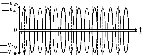
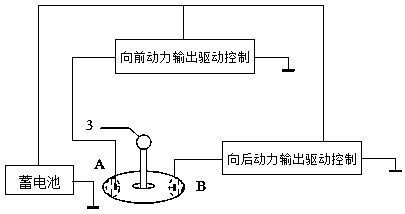
[0035] Example 1: The hypersonic inner surface plasma DC pulse wind tunnel airflow boosting system is composed of IN1 electrode strip (2), IN2 dual electrode strip (3), control push rod (4) and DC pulse plasma drive control system;

[0036] The entire outer surface of the wind tunnel tube is made of insulating ceramic material; the outer surface is embedded with two pairs of electrode strips at vertical intervals along the direction of movement, and each pair of electrode strips is composed of IN1 electrode strips (2) and IN2 pair electrode strips (3). IN1 electrode strips (2) and IN2 paired electrode strips (3) are arranged parallel to each other; the electrode strips embedded in the ceramic surface layer are polished together with the inner and outer shell layers of the wind tunnel pipe to form a smooth surface;

[0037] Auxiliary propulsion and attitude control are achieved through plasma DC pulses on the inner surface of the wind tunnel, and two sets of DC pulse plasma driv...


PUM


Abstract

The invention relates to a hypersonic velocity inner surface plasma direct-current pulse wind tunnel airflow propulsion system and belongs to the field of power technologies in wind tunnels. Two pairsof annular electrode strips are vertically inserted into the outer surface of a wind tunnel at intervals along a moving direction; each pair of electrode strips is composed of electrode strips IN1 and dual electrode strips IN2; auxiliary propulsion and attitude control are realized through plasma direct-current pulses on the inner surface of the wind tunnel; two sets of direct-current pulse plasma drives are driven; the polarity of the voltage pulses of the electrodes IN1 is opposite to the polarity of the voltage pulses of the electrodes IN2, and the double direct-current pulse plasma drivesare driven; direct-current pulse plasmas are adopted to drive a PWM modulation system; an AT89S52 single-chip microcomputer is adopted as a control core; the system is composed of a command input module, an LED display module and a direct-current pulse power amplification driving module; digital precision control is realized; a propulsion mode in the wind tunnel is completely changed; more energycan be saved; and the source of the inner wall resistance of the wind tunnel is eliminated in principle. The system has great development potential.

Description

technical field [0001] The invention relates to a hypersonic inner surface plasma DC pulsed wind tunnel airflow boosting propulsion system, which belongs to the technical field of wind tunnel experiments. Background technique [0002] Technical difficulties of hypersonic wind tunnels: (1) Power system: High-speed airflow is compressed and input into the pipeline of the sealed wind system. The high-speed airflow will generate shock waves and turbulent flow, making the airflow unstable; (2) Hypersonic wind tunnel Another difficulty encountered during the development process was the problem of aerodynamic heating, the so-called thermal barrier. Due to the effect of shock wave and viscosity on the inner wall of the wind tunnel, the temperature of the surrounding air rises sharply, forming a severe aerodynamic heating environment. In order to overcome the thermal barrier, the aerodynamic heating rate entering the wind tunnel pipe, that is, the heat flow, should be reduced as much...

Claims


Application Information

Patent Timeline
Patent Type & Authority Applications(China)
IPC IPC(8): G01M9/06
Inventor 陈蜀乔
Owner 广州精秀热工设备有限公司
Learn More