An optical cable transfer box with dust removal and heat dissipation functions

A fiber optic cable transfer box, functional technology, applied to the device for catching or killing insects, fiber mechanical structure, animal husbandry, etc., can solve the problems of extra fan drive, internal electrical internal electrical short circuit, affecting insect prevention and exhaust effect, etc. , to achieve the effect of improving dust removal performance and reducing frequency of use

Active Publication Date: 2020-07-28
HANGZHOU ZHONGKAI TELECOMM EQUIP
View PDF10 Cites 0 Cited by
  • Summary
  • Abstract
  • Description
  • Claims
  • Application Information

AI Technical Summary

Problems solved by technology

[0003] The fiber optic cable junction box will generate a lot of heat during use. If the heat is not discharged in time, it will affect the service life of the internal electrical appliances and cause serious internal electrical short circuits. Therefore, it is necessary to use a fan to cool the interior of the fiber optic cable junction box. The long-term work of the fan needs to be done regularly. Replacement and fan drives require additional power. The electrical work inside the optical cable transfer box needs to work in an environment with less dust. The existing optical cable transfer box has poor dust removal performance, and the insect-proof net at the bottom of the optical cable transfer box is prone to blockage after long-term use, affecting insect protection. and exhaust effects

Method used


Image

  • An optical cable transfer box with dust removal and heat dissipation functions
  • An optical cable transfer box with dust removal and heat dissipation functions
  • An optical cable transfer box with dust removal and heat dissipation functions

Examples


Embodiment Construction

[0032] The technical solutions in the embodiments of the present invention will be clearly and completely described below in conjunction with the embodiments of the present invention. Apparently, the described embodiments are only some of the embodiments of the present invention, not all of them. Based on the embodiments of the present invention, all other embodiments obtained by persons of ordinary skill in the art without creative efforts fall within the protection scope of the present invention.

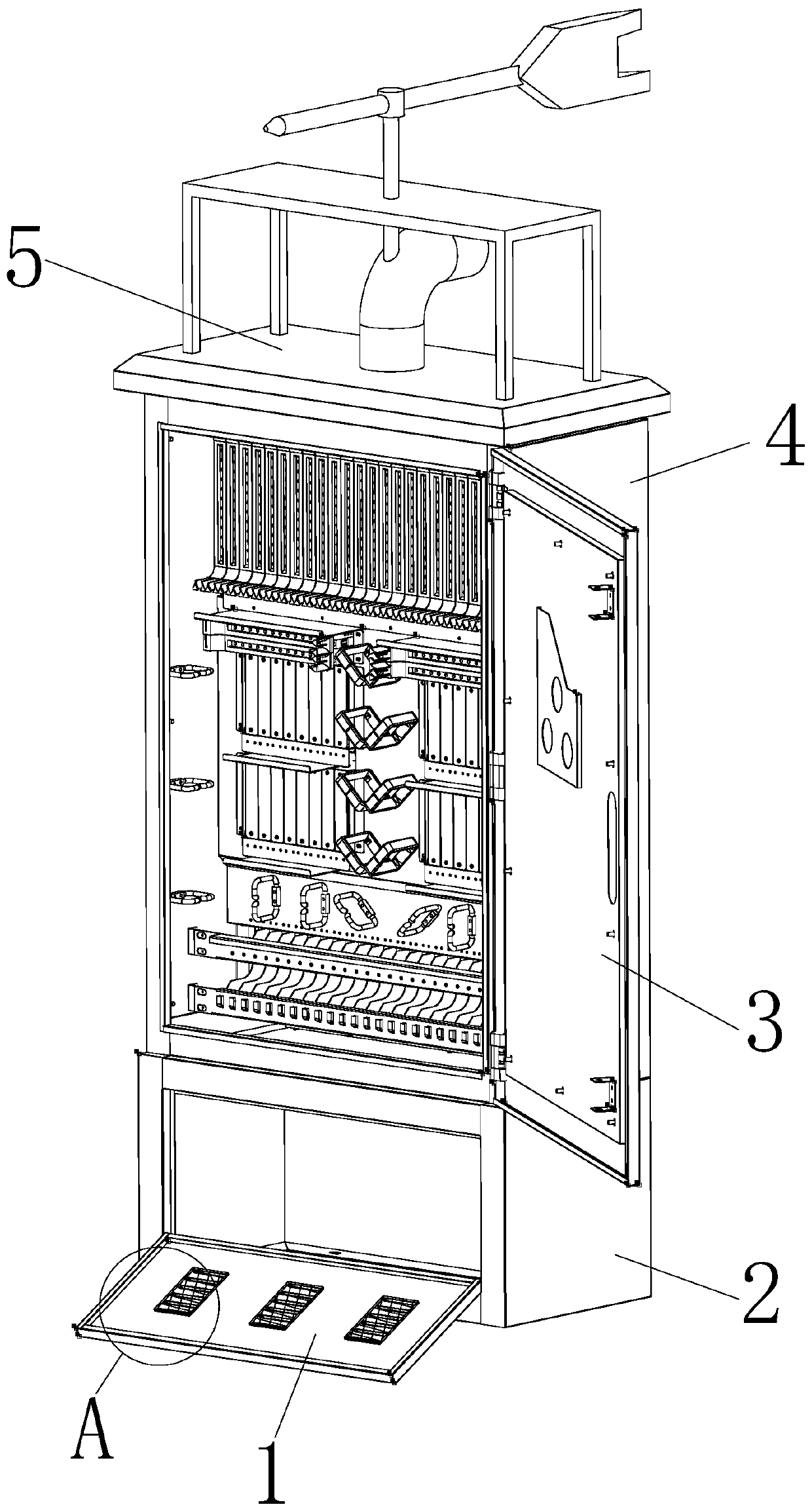
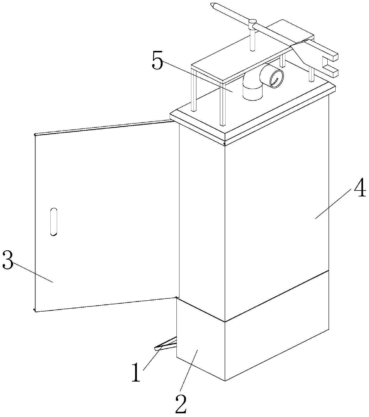
[0033] refer to Figure 1-8 , a fiber optic cable transfer box with dust removal and heat dissipation functions, comprising a lower box 2, a side flip door 3 and an upper box 4, the upper part of the lower box 2 is welded with an upper box 4, and the front of the upper box 4 is rotated by a hinge A side flip door 3 is connected, and the top of the upper box body 4 is welded and fixed with an upper cover body 5. The upper cover body 5 includes a top cover 10 that is arranged on the...


PUM


Abstract

The invention discloses an optical cable splice box with dust removal and heat dissipation functions. The optical cable splice box comprises a lower box body, a side turnover door and an upper box body, wherein the upper box body is welded to the upper part of the lower box body, and the side turnover door is rotatably connected to the front face of the upper box body through hinges. According tothe optical cable splice box, an air intake elbow pipe is driven to align with the wind intake direction through contacting of a paddle board and an external air flow, and the external air flow is ledinto the upper box body for heat dissipation, so that the use frequency of a draught fan is lowered, the service life of the draught fan is prolonged, and energy is saved. A rubber ball is driven toperiodically impact by a reverse air flow generated by driving the draught fan, and a first airbag pad and a second airbag pad have elasticity, so that dust is accelerated to be dropped from the upperpart of a purification mesh enclosure and the dust removal performance of the optical cable splice box is improved, an insulating cover is connected to the position, corresponding to window-shades, of the inner wall of a lower turnover door, and when a mosquito is killed, the body of the mosquito stuck in a high-voltage shock net can be discharged outward through conduction of the insulating cover to ensure the effects of mosquito prevention and exhausting.

Description

technical field [0001] The invention relates to the technical field of optical cable transfer boxes, in particular to an optical cable transfer box with dust removal and heat dissipation functions. Background technique [0002] In the construction of local optical cable network, in order to improve the utilization rate of the optical cable backbone, reduce the number of openings for the introduction of optical cable connectors, and effectively improve the safety and reliability of the optical cable, it is recommended to set up the necessary optical cable transfer box on the main route of the optical cable. The optical cable transfer box is mainly used for the interface equipment at the junction of the main optical cable and the distribution optical cable in the optical cable access network. The structure of the optical cable transfer box is mainly composed of the box body, internal metal workpieces, optical fiber active connectors and spare accessories. According to differe...

Claims


Application Information

Patent Timeline
Patent Type & Authority Patents(China)
IPC IPC(8): G02B6/44A01M1/22
Inventor 羊水法陈炯李孝儿蒋剑飞
Owner HANGZHOU ZHONGKAI TELECOMM EQUIP
Why Eureka
Try Eureka