[0034] What is set forth below is what is presently considered to be the preferred embodiment, or best representative example, of the claimed invention. Any alteration or modification which substantially alters function, purpose, structure, or result, having considered future and present representations or modifications of the embodiments and preferred embodiments, is intended to be covered by the claims of this patent. Preferred embodiments of the invention will now be described, by way of example only, with reference to the accompanying drawings.
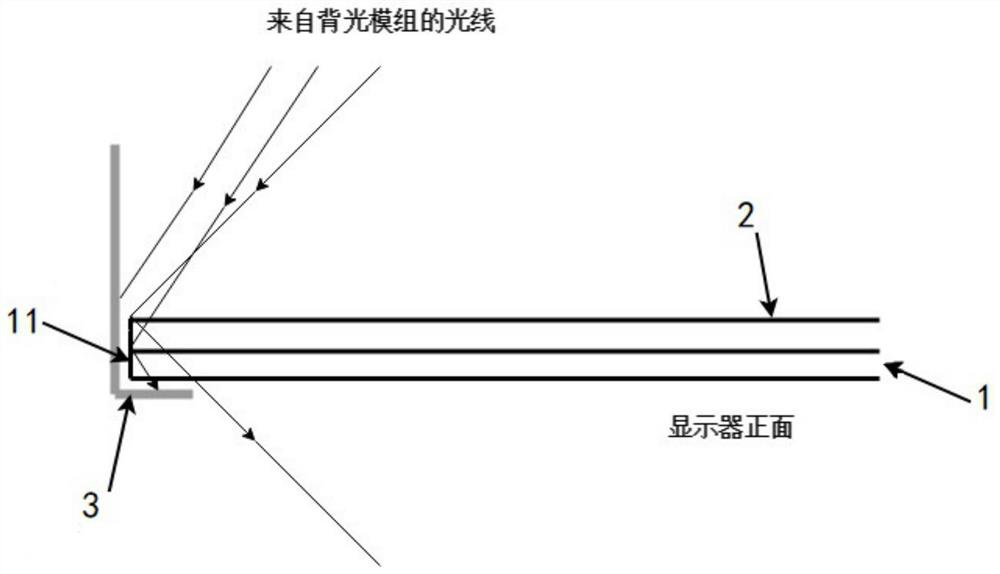
[0035] Figure 5 A schematic diagram showing the refraction and reflection of light on the end surface of the cover glass. exist Figure 5 The end surface 11 of the cover glass 1 shown in is a plane, and when the light falls on the end surface, it will be refracted or reflected depending on its incident angle. Assume that the refractive index of the optically rarefied medium is n 1 , the refractive index of the optically dense medium is n 2 , the incident angle is i, and the outgoing angle is r, then the relationship between the incident angle and the outgoing angle is shown in the following formula (1):
[0036] no 1 sin i=n 2 sin r...(1)
[0037] The incident angle i of the light on the end face of the cover glass 1 When it is less than the critical angle c, most of the light rays will be refracted at the angle r 1 penetrating the end face, the remaining few parts will be at the same angle r 1 reflection; angle of incidence i 2 When it is greater than the critical angle c, it will be at the same angle, that is, r 2 = i 2 Total internal reflection; when the incident angle i is just equal to the critical angle c, the outgoing angle r is 90°, and the light will proceed along the critical surface of the glass end, that is to say, the critical angle can be obtained from the following formula (2):
[0038] c=i=arxsin(n 2 / n 1 /sin r)...(2)
[0039] For example, since the optically rarefied medium is air, n 1 = 1, the optically dense medium is cover glass, generally n2 ≈1.6 (this value is not a well-defined value, here is only for the convenience of calculation),
[0040] 1 sin 90°=1.6 sinc...(3)
[0041] c≈38.68°...(4)
[0042] Therefore, when the incident angle between the end surface of the cover glass and the light is less than 38.68°, most of the light penetrates the end surface in the form of refraction, and when the incident angle between the end surface of the cover glass and the light is greater than 38.68°, the light will be totally reflected in the end surface.
[0043] The present invention designs microstructures 12 on the peripheral end surfaces 11 of the cover glass 1 according to the above-mentioned technical principles. When the light passes through the LCD panel from the backlight module, enters the cover glass and reaches the end surface of the glass, the microstructure on the end surface allows most of the light to refract and pass through, or reflect the light back to the direction of the LCD panel and the backlight module. Reflections to the front of the display are not tolerated. Moreover, the light penetrating the microstructure will scatter when it falls on the rough inner surface of the display frame. If the brightness is not concentrated, there will be no light leakage, and the light reflected back to the direction of the liquid crystal panel and the backlight module will not overflow from the front of the screen.
[0044] Image 6 A schematic diagram showing one of the geometric feature designs of the microstructure of the end face of the cover glass of the liquid crystal display according to an embodiment of the present invention, Figure 8 shows the basis Image 6 The partial enlarged schematic diagram of the microstructure is shown, and the refraction and reflection lines of the light at the microstructure are shown. It can be seen that the cover glass 1 is arranged on the opposite side of the display liquid crystal panel 2 from the side receiving the light from the backlight module, and the microstructures 12 are formed on the four sides of the cover glass 1 on the end faces 11 along the Arranged in the thickness direction of the cover glass 1 , it is an exemplary regular zigzag structure of equilateral triangles. This non-planar structure can make most of the light rays pass through the end face in the form of refraction and enter the display frame 3 when the incident angle is smaller than the critical angle c, such as 38.68° mentioned above, and the incident angle is greater than the critical angle c, such as the above At the angle of 38.68° mentioned above, the light will be totally reflected in the end face and reflected back into the cover glass 1 instead of going out from the front of the display.
[0045] Figure 7 A schematic diagram showing another geometric feature design of the microstructure of the end surface of the cover glass of the liquid crystal display according to another embodiment of the present invention, Figure 9 shows the basis Figure 7 The partial enlarged schematic diagram of the microstructure is shown, and the refraction and reflection lines of the light at the microstructure are shown. This microstructure 12 is also a regular zigzag structure arranged along the thickness direction of the cover glass 1, but the shape is an equilateral triangle, which further shows that when the incident angle is smaller than the critical angle c, such as described above The light at 38.68° of the angle all penetrates the end surface in the form of refraction, and is reflected into the display frame 3 again through the outer edge.
[0046] The design of the microstructure is related to the incident angle of the light on the end face of the cover glass. Adding a non-planar microstructure with regular geometric features on the glass end face can change the original angle of the glass end face perpendicular to the display surface and achieve control. The purpose of the final direction of light, therefore, the microstructure designed in the present invention includes but is not limited to the above-mentioned attached Figures 6 to 9 The structure of the illustrated geometric features can also include any microstructure that can achieve the above functions, such as Figure 10 The illustrated microstructures 12 of various geometric features may be, for example, regular and continuous zigzags, wedges, spherical arcs, and the like. Moreover, when the microstructure close to the display frame 3 is not sharp-edged but small curved or flat, the panel and cover glass can be better protected against collisions and the like.
[0047] The cover glass 1 is made of glass material, and the above-mentioned microstructure 12 can be integrally formed with the cover glass, and the end surface of the cover glass 1 is ground by a grinding whetstone to form the microstructure. In another embodiment, the above-mentioned microstructure can also be formed by a controlled chemical etching method.
[0048] In other optional embodiments, an optical-grade UV curable resin having the same refractive index as the material of the cover glass can be selected to form the above-mentioned microstructure 12 . Since the refractive index of the resin material is the same as that of the cover glass, light will not be refracted or reflected at the interface between the cover glass and the resin material, but will be refracted or reflected on the surface of the microstructure as described above after penetrating the interface, so as to achieve The purpose of controlling the final direction of light. Figure 11 It shows an example diagram of fabricating microstructures using UV precision coating molding method according to an embodiment of the present invention. like Figure 11 As shown, the application of UV precision coating molding technology directly adds optical-grade UV curable resin to the end face 11 of the cover glass 1. First, the optical-grade UV curable resin is coated along the end faces 11 of the four sides of the cover glass 1 by rollers; then , use ultraviolet light (UV) to cure the resin, and firmly adhere to the end surface 11 of the cover glass 1 .
[0049] The invention does not involve complex structures and assembly steps, and does not need to add additional parts, so it can be directly applied to actual production without modifying the design of the product. Because the design can effectively prevent the reflection of light on the four sides of the cover glass facing the front of the screen, even if the masking tape is omitted, there will be no light leakage problem, so it is very suitable for 2D and 3D LCD TVs, monitors, and splicing TVs with narrow and ultra-narrow bezels. wall products.
[0050] The above description is not intended to limit the meaning or scope of the words used in the following claims which define the invention. Rather, descriptions and illustrations are provided to assist in understanding the various embodiments. It is anticipated that future modifications in structure, function, or result may exist without substantive changes and all such insubstantial changes in the claims are intended to be covered by the claims. Therefore, while preferred embodiments of the present invention have been illustrated and described, it will be understood by those skilled in the art that various changes and modifications can be made without departing from the invention as claimed. Additionally, although the terms "claimed invention" or "present invention" are sometimes used herein in the singular, it will be understood that there may be multiple inventions as described and claimed.