

A current-voltage conversion circuit for sensors
A current-voltage conversion and sensor technology, which is applied in the direction of instruments, scientific instruments, and electric variable adjustment, can solve the problems of poor noise performance, high noise performance requirements of sensor application circuits, and limited dynamic range performance of amplifiers, etc.
- Summary
- Abstract
- Description
- Claims
- Application Information
AI Technical Summary
Problems solved by technology
Method used
Image


Examples
Embodiment
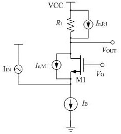
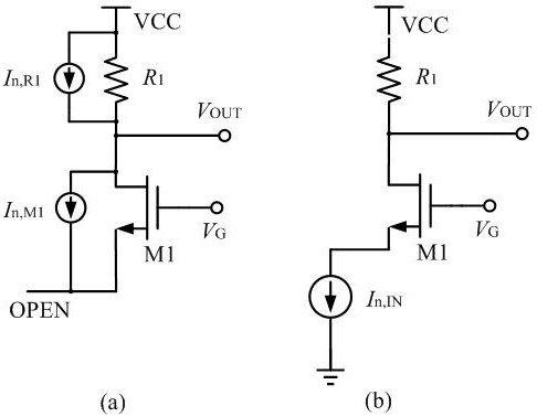
[0023] Such as image 3 As shown, a current-voltage conversion circuit for sensors, including the output terminal V of the current-voltage conversion circuit OUT and input I IN ; The output V OUT and input I IN A cascode input stage and a source follower are connected between them; the cascode input stage is composed of transistors M1, M2 and resistor R1; the source follower is composed of transistors M3, M4 and a load resistor Composed of R2; the cascode input stage is provided with a bias circuit, and the bias circuit is an auxiliary voltage amplifier; the auxiliary voltage amplifier is composed of a transistor M5 and a resistor R3.
[0024] The transistor M2 and the resistor R1 are connected in parallel with a fixed direct current source I0, the fixed direct current source I0 is connected to the drain of the transistor M1, and injects the direct current source I0 into the transistor M1.
[0025] The transconductance of the transistor M1 is greater than that of the trans...
PUM
 Abstract
Description
Claims
Application Information