
Method for extending length of cable

A cable length and cable technology, applied in the direction of circuits, electrical components, circuit/collector components, etc., can solve problems such as easy breakdown, large joint size, and large difference between the insulation layer and the original cable, and achieve reliability and High stability, good waterproof performance, no visible discharge effect

Inactive Publication Date: 2019-06-07
嘉兴新缆电缆股份有限公司
View PDF8 Cites 6 Cited by
  • Summary
  • Abstract
  • Description
  • Claims
  • Application Information

AI Technical Summary

Problems solved by technology

[0003] In the prior art, the conductor connection method is to insert the conductor into the intermediate connecting pipe for crimping; the cable conductor adopts this connection method, which has the following problems: 1. The size of the intermediate connecting pipe is larger than the diameter of the conductor, which makes the joint size too large. 2. Since the intermediate connecting tube is used for crimping, the intermediate connecting tube and the wire are contact conductive, and the oxide layer on the surface of the conductor will make the conductivity lower than that of the original cable conductor, and the resistance here will be larger , when working with high current, the connection is very easy to heat and cause damage to the line; 3. The connection method is crimping, so the crimping force has a great influence on the quality of the connection, which will also lead to poor connection quality and stability 4. Since multiple wires in the conductor are connected through the intermediate connecting pipe at the same time, this makes the cable at the cable joint high in hardness and difficult to bend, which brings certain difficulties to the laying of the line, and frequently received during the installation process. Easy to break when bent
[0005] It has the following disadvantages in adopting the method of the prior art to restore the insulation layer: 1, because it adopts the shrinkage method to be tightly placed on the outer layer of the cable conductor for insulation, there is a gap between the insulation layer and the conductor that cannot be avoided, so in the water environment The failure rate is high during operation; 2. The joint is too large and unsightly; 3. There is no power plant shielding, the electric field distribution is uneven, the discharge is too large, and the operation process is easy to break down; 4. The insulation layer of the joint part is different from the original cable. Large, which makes the insulation consistency at the joint poor and prone to failure

Method used


Image

  • Method for extending length of cable
  • Method for extending length of cable
  • Method for extending length of cable

Examples


Embodiment Construction

[0055] In order to make the purpose, technical solutions and advantages of this application clearer, the technical solutions in the embodiments will be clearly and completely described below in conjunction with the accompanying drawings in the embodiments. Obviously, the described embodiments are only a part of the application Examples, not all examples.

[0056] A method of extending the length of a cable comprising

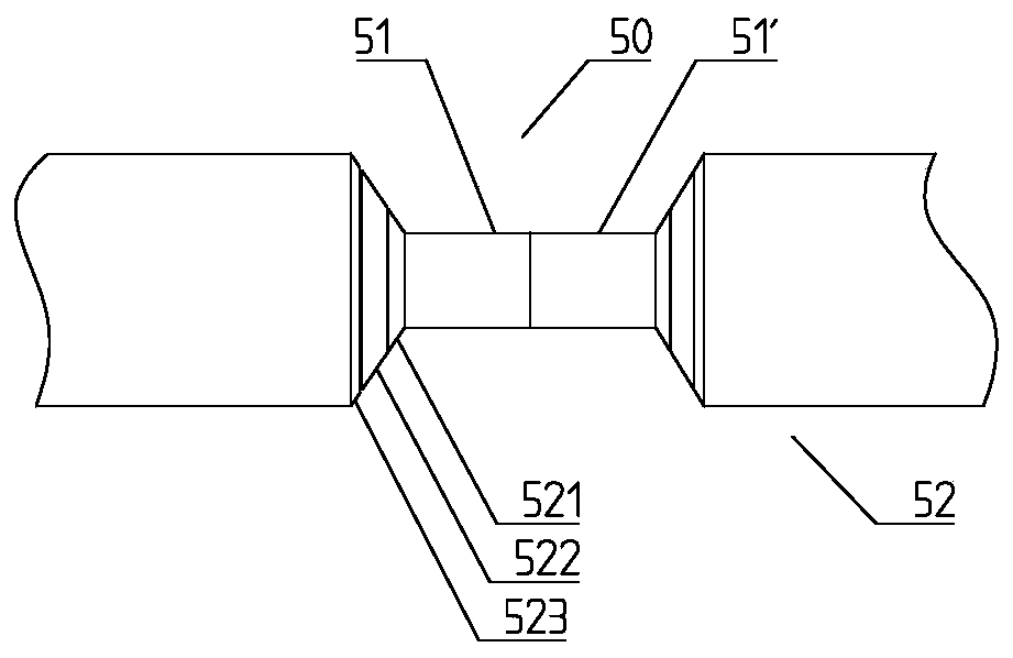
[0057] S1: Cut the insulating layer at the end of the two cables to be connected, and expose the conductor of the inner wire; specifically, remove the insulating layer of the cable; the total length of the end insulating layer 52 of the two cables to be connected is 30-35cm , that is, the length of each end is 15-17.5cm, the incision of the insulating layer 52 is a cone angle, and the angle is preferably 30 degrees;

[0058]S2: Use flame-retardant and refractory cloth to fasten the bodies of the two cables close to the cutout for protection;

[0059] S3: Safel...


PUM


Abstract

The invention discloses a method for extending the length of a cable. The method comprises the following steps of: S1: cutting insulation layers at end portions of two cables to be connected to exposeconductors of the internal wires; S2: employing flame-retardant and fire-resistant cloth to fasten bodies, close to notches, of the two cables for protection; S3: allowing the mutual connection endsof the two cables to be made to adaptive anode head and cathode head, opening the cathode head layer by layer outwards to allow the wire in the innermost layer to be exposed, and performing welding from the wire in the innermost layer one by one and layer by layer; S4: performing molding for the insulation layers in the connected conductors through adoption of an injection molding method; and S5:performing molding for the outer sheaths of the connected conductors through adoption of an injection molding method. The silver materials with the electrical resistivity lower than these of the cables are employed layer by layer and one by one for brass soldering to allow the conductivity at the welding not to be lower than these of the conductor themselves; the connector insulation layer can bein fusion and cross-linkage with the insulation layer of an original cable well to allow the insulation layer at the connector and the insulation layer of the original cable to form an integrated structure, and the electrical properties of the connector are the same as these of the original cable.

Description

technical field [0001] The invention belongs to the technical field of cable connection, and in particular relates to a method for extending cable length. Background technique [0002] Due to the limited length of power cables, there are always several joints in the middle of a power cable line. Only when the power cables are connected can they work normally. This accessory for connecting power cables is called a cable shrinkable intermediate head. [0003] In the prior art, the conductor connection method is to insert the conductor into the intermediate connecting pipe for crimping; the cable conductor adopts this connection method, which has the following problems: 1. The size of the intermediate connecting pipe is larger than the diameter of the conductor, which makes the joint size too large. 2. Since the intermediate connecting tube is used for crimping, the intermediate connecting tube and the wire are contact conductive, and the oxide layer on the surface of the condu...

Claims


Application Information

Patent Timeline
Patent Type & Authority Applications(China)
IPC IPC(8): H01R43/02H01R43/033
Inventor 王志隆郑茂青
Owner 嘉兴新缆电缆股份有限公司
Learn More