Eureka AIR delivers breakthrough ideas for toughest innovation challenges, trusted by R&D personnel around the world.

Wireless electric energy transmission system and preceding-stage high-frequency power source design method thereof

A technology of wireless energy transmission and high-frequency power supply, which is applied in the direction of electrical components, circuit devices, and output power conversion devices, and can solve problems such as electromagnetic interference, lack of analysis and discussion of power electronic devices, and high cost, so as to reduce the impact, Effects of area reduction and switching loss reduction

Active Publication Date: 2019-06-07
NORTHEASTERN UNIV
View PDF5 Cites 0 Cited by
  • Summary
  • Abstract
  • Description
  • Claims
  • Application Information

AI Technical Summary

Problems solved by technology

However, there are still many problems such as electromagnetic interference, transmission distance, and high cost.
At the same time, most of the research on the wireless power transmission system only analyzes and designs the coil and its compensation network, studies its transmission mechanism and transmission efficiency, and lacks the analysis and discussion of the power electronic devices required for it.

Method used


Image

  • Wireless electric energy transmission system and preceding-stage high-frequency power source design method thereof
  • Wireless electric energy transmission system and preceding-stage high-frequency power source design method thereof
  • Wireless electric energy transmission system and preceding-stage high-frequency power source design method thereof

Examples


Embodiment Construction

[0020] The specific implementation manners of the present invention will be further described in detail below in conjunction with the accompanying drawings and embodiments. The following examples are used to illustrate the present invention, but are not intended to limit the scope of the present invention.

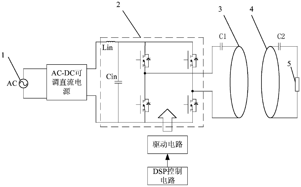
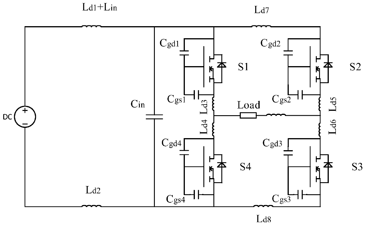
[0021] A wireless power transmission system, which realizes the wireless transmission of electric energy in the form of magnetic coupling resonance, such as figure 1 with figure 2 As shown, the overall system includes: an AC-DC adjustable DC power supply, a high-frequency power supply device, a transmitting coil 3 and a receiving coil 4; the high-frequency power supply device includes a high-frequency inverter circuit 2, a drive circuit and a DSP control circuit; The AC-DC adjustable DC power supply converts the AC low-frequency commercial power 1 into the required DC power, which is used as the input DC voltage of the high-frequency inverter circuit 2; the high-frequenc...


PUM


Abstract

The present invention provides a wireless electric energy transmission system and a preceding-stage high-frequency power source design method thereof, and relates to the technical field of wireless electric energy transmission. The system comprises an AC-DC adjustable direct current power source configured to convert an alternating current low-frequency electric supply to an input direct voltage of a high-frequency inverter circuit; a high-frequency inverter circuit taken as a preceding-stage high-frequency power source of the wireless electric energy transmission system; a DSP control circuitconfigured to modulate the on-off of a switching device in the high-frequency inverter circuit; a drive circuit configured to amplify DSP signals and convert the DSP signals to drive signals configured to drive the switching device; a receiving coil taken as a transmitting coil as a load of the high-frequency inverter circuit; and a receiving coil directly connected with the a load requiring power to form a load circuit loop. The present invention further provides a method for design of the preceding-stage high-frequency power source in the wireless electric energy transmission system. The wireless electric energy transmission system and the preceding-stage high-frequency power source design method thereof greatly improve the working frequency of the wireless electric energy transmissionsystem so as to improve the transmission distance and the efficiency between the coils.

Description

technical field [0001] The present invention relates to the technical field of wireless power transmission, in particular to a wireless power transmission system and a design method for a front-stage high-frequency power supply thereof. Background technique [0002] Wireless power transmission, also known as contactless power transmission, refers to a transmission method that transmits power from the power source to the load without a direct electrical connection. In recent years, due to the problems of contact wire friction, exposure, and aging in traditional wired power transmission methods, research on wireless power transmission technology has attracted more and more attention. In 2007, scientists at the Massachusetts Institute of Technology proposed a magnetically coupled resonant wireless power transmission technology, which has attracted widespread attention and research at home and abroad, and is currently one of the most promising technologies. Compared with the tr...

Claims


Application Information

Patent Timeline
IPC IPC(8): H02J50/12H02J50/70H02M5/458
Inventor 杨东升程子鑫张化光李华周博文刘鑫蕊杨珺刘金海马大中元席希田江为
Owner NORTHEASTERN UNIV
Why Eureka
Eureka Blog
Learn More