
Permanent magnet/reluctance dual-rotor low-speed and high-torque synchronous motor and control system thereof

A synchronous motor, double rotor technology, applied in the direction of electronic commutation motor control, control system, vector control system, etc., can solve the problems of low operation efficiency, high cost, poor system reliability, etc., and achieve high material utilization and low cost. , Improve the effect of reluctance torque

Pending Publication Date: 2019-06-07
SHENYANG POLYTECHNIC UNIV
View PDF0 Cites 3 Cited by
  • Summary
  • Abstract
  • Description
  • Claims
  • Application Information

AI Technical Summary

Problems solved by technology

[0004] Purpose of the invention: The present invention provides a permanent magnet / reluctance dual-rotor low-speed high-torque synchronous motor and its control system. , high cost issues

Method used


Image

  • Permanent magnet/reluctance dual-rotor low-speed and high-torque synchronous motor and control system thereof
  • Permanent magnet/reluctance dual-rotor low-speed and high-torque synchronous motor and control system thereof
  • Permanent magnet/reluctance dual-rotor low-speed and high-torque synchronous motor and control system thereof

Examples


Embodiment Construction

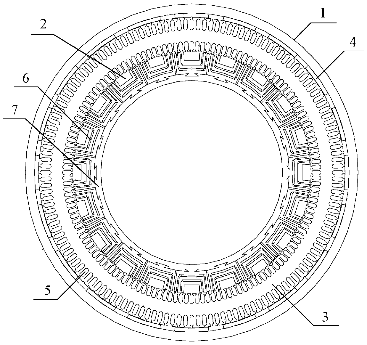
[0032] The permanent magnet / reluctance dual-rotor low-speed high-torque synchronous motor is characterized in that: the synchronous motor is mainly composed of an outer rotor (1), an inner rotor (2) and a stator (3); the stator (3) is arranged on the outer rotor (1 ) and the inner rotor (2);

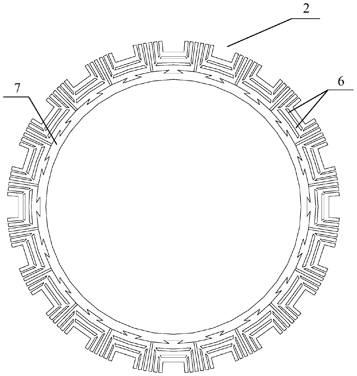
[0033] The inner rotor (2) includes a magnetic isolation ring (7) (2-1) and a magnetic barrier reluctance rotor structure (6), and the magnetic barrier reluctance rotor structure (6) is composed of a magnetic permeable layer (6-1) and The non-magnetic-permeable layers (6-2) are alternately formed, each magnetic barrier reluctance rotor structure (6) is fixed on the outer wall of the magnetic isolation ring (7) through the dovetail groove, and the magnetic barrier reluctance rotor structure (6) is set Between the magnetic isolation ring (7) and the stator (3);

[0034] A permanent magnet (4) is arranged inside the outer rotor (1);

[0035] The inner and outer surfaces of the stator (3) ...


PUM


Abstract

The present invention provides a permanent magnet / reluctance dual-rotor low-speed and high-torque synchronous motor and a control system thereof. The synchronous motor is mainly formed by an outer rotor (1), an inner rotor (2) and a stator (3). The stator (3) is arranged between the outer rotor (1) and the inner rotor (2). The method estimates the position of a reluctance rotor to obtain the position of the whole rotor to achieve sensorless control. The provided sensorless vector control method does not need coordinate transformation, is simple in structure and can overcome the problems of thecomplexity of the vector control and the high dependence on the motor parameters.

Description

Technical field: [0001] The invention relates to a permanent magnet / reluctance dual-rotor low-speed high-torque synchronous motor and a control system thereof. The invention belongs to the field of motor design and its control system. Background technique: [0002] There are a large number of equipment in modern industry that require low-speed and high-torque transmission systems, such as CNC machine tools, heavy mining machinery, oil drilling machinery, large-scale industrial conveyor belts, and lifting equipment. Such systems are typical high-energy-consuming electromechanical equipment. Electricity accounts for about 10% of the total electricity consumption in industry. At present, most of my country's low-speed and high-torque transmission equipment adopts the drive mode of "conventional speed motor + reduction gear mechanism", but the extra reduction transmission link will not only make the drive system bulky, increase maintenance costs, and reduce system reliability a...

Claims


Application Information

Patent Timeline
Patent Type & Authority Applications(China)
IPC IPC(8): H02K16/02H02K1/22H02K1/27H02K1/16H02P21/24H02P21/18H02P25/022
Inventor 刘光伟于思洋金石张凤阁戴睿王皓
Owner SHENYANG POLYTECHNIC UNIV
Learn More