

Stator permanent magnet type bipolar magnetic-aggregation type transverse flux permanent magnet synchronous motor
A permanent magnet synchronous motor, transverse magnetic flux technology, applied in the direction of synchronous machine, synchronous machine parts, electrical components, etc., can solve the problems of large cogging torque, low stator space utilization, high cost, and improve torque Effects of density and power, flexible motor structure design, and low cost
- Summary
- Abstract
- Description
- Claims
- Application Information
AI Technical Summary
Problems solved by technology
Method used
Image

Examples
Embodiment 1
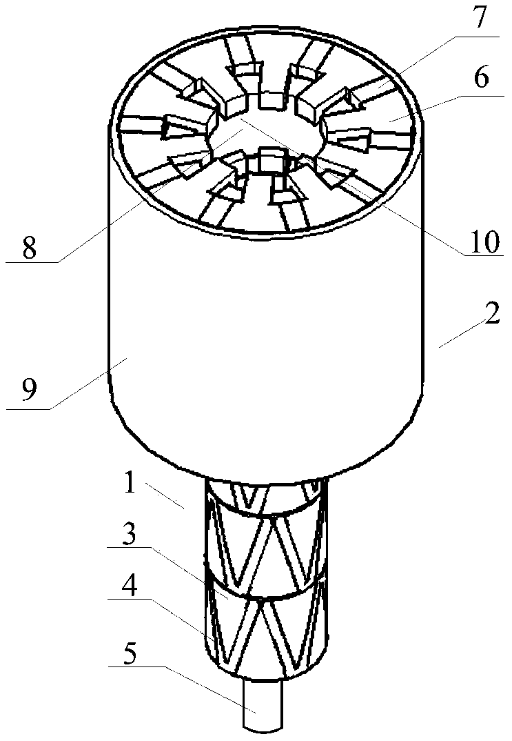
[0041] Such as figure 1 and figure 2 As shown, the bipolar transverse flux permanent magnet synchronous motor in Embodiment 1 of the present invention is a three-phase 10-pole stator permanent magnet type bipolar magnetic concentration type transverse flux permanent magnet synchronous motor, which includes a rotor part 1 and Stator part 2.
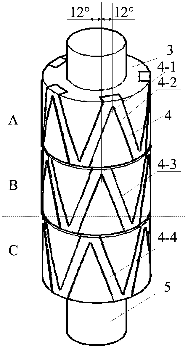
[0042] It includes a rotor support body 3, a rotor core 4 and a rotor shaft 5, the rotor core 4 is embedded in the outer surface of the rotor support body 3, and the rotor support body 3 is fixed on the rotor shaft 5;
[0043] The rotor cores 4 belong to three phases A, B, and C. The rotor cores 4 of each phase are evenly distributed along the circumference in the shape of isosceles triangular waves. The rotor cores 4 of each phase form a total of 10 isosceles triangles. The adjacent Two iron cores constitute the two sides of the triangular wave, such as figure 2 The rotor core 4-1 and the rotor core 4-2 are shown. Such as figure 2 A...
Embodiment 2
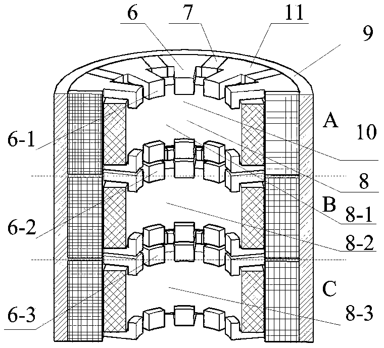
[0053] Such as Figure 15 , 16 As shown in and 17, the difference between the first embodiment and the second embodiment of the present invention is mainly reflected in that the three-phase stator units are staggered in the same direction along the axial direction by 12°, that is, the stator core 6 and the permanent magnet 7 of each phase are also staggered in the same direction in turn The angle is 12°, and the rotor units of each phase do not differ in angle, and they are all aligned. Such as Figure 16 As shown, the B-phase stator is staggered by 12° from the A-phase stator as a whole, and the C-phase stator is 12° from the B-phase stator as a whole, that is, 24° from the A-phase stator as a whole.
[0054] The same as the first embodiment, the 10 "C" shaped stator cores 6 and 10 permanent magnets 7 in each phase are still distributed in a staggered manner along the circumferential direction and arranged evenly, and all the permanent magnets 7 are magnetized tangentially ...
PUM
 Abstract
Description
Claims
Application Information