
A reciprocating steel plate cutting device based on the principle of crank slider

A technology of crank slider and cutting device, which is applied to sawing machine, feeding device, metal sawing equipment, etc., can solve the problems of high labor intensity, large area and fire occurrence.

Active Publication Date: 2021-04-30
广西桂盾人防工程有限公司
View PDF12 Cites 2 Cited by
  • Summary
  • Abstract
  • Description
  • Claims
  • Application Information

AI Technical Summary

Problems solved by technology

[0003] After the steel plate is cast out of the furnace, the area is often large, which is not conducive to handling and transportation. In the actual production and application process, it is usually cut to make it into a small plate that is more convenient for transportation. The existing steel plate cutting is due to its large area. , mostly by gas welding and cutting, labor-intensive, and there is a risk of fire

Method used


Image

  • A reciprocating steel plate cutting device based on the principle of crank slider
  • A reciprocating steel plate cutting device based on the principle of crank slider
  • A reciprocating steel plate cutting device based on the principle of crank slider

Examples


Embodiment 1

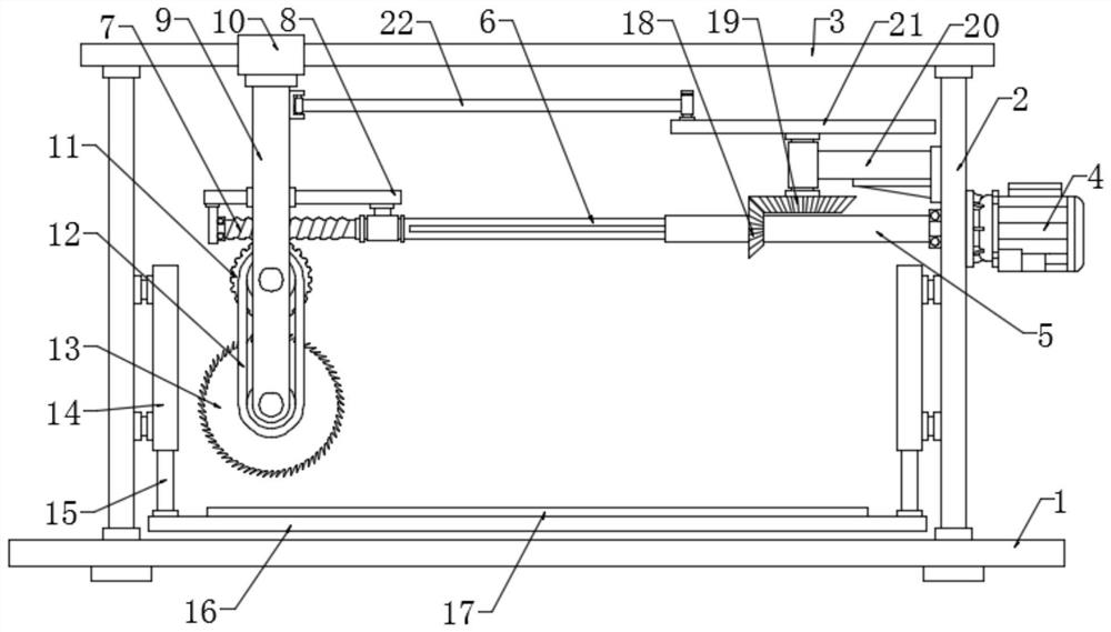
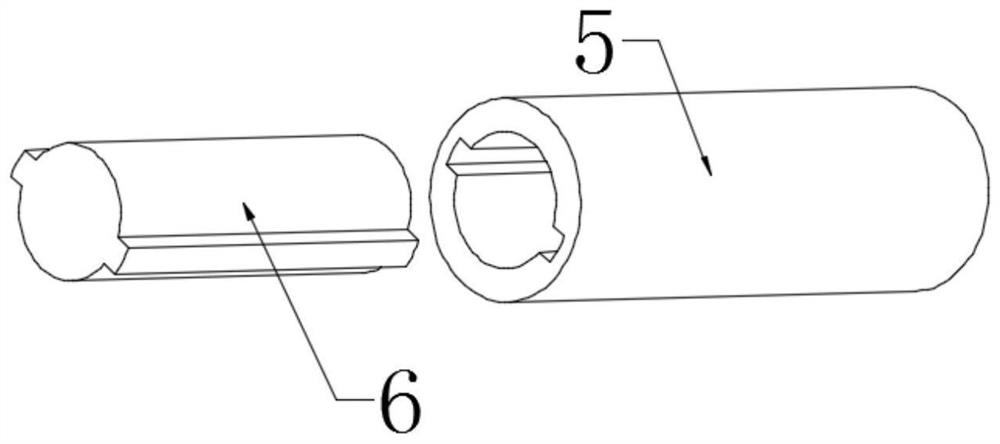
[0022] see Figure 1~3 , in an embodiment of the present invention, a reciprocating steel plate cutting device based on the slider crank principle includes a pallet 1, a sleeve 5, a boom 9, a cutting wheel 13 and a turntable 21; the two sides above the pallet 1 are respectively A column 2 is fixedly connected, and a guide rod 3 is fixedly connected between the columns 2 on both sides, and a drive motor 4 is fixedly installed on the flange of one side column 2, and the output end of the drive motor 4 rotates to connect the sleeve 5, and the sleeve 5 is socketed The stepped shaft 6, it should be noted that the sleeve 5 is a hollow shaft, two grooves are symmetrically arranged on its inner wall, and two convex lines are symmetrically arranged on the outer wall of the stepped shaft 6, and the convex lines are fitted on the inner wall of the sleeve 5 In the groove, the sleeve 5 can drive the stepped shaft 6 to rotate through the fitted convex strip and the groove, and the stepped s...

Embodiment 2

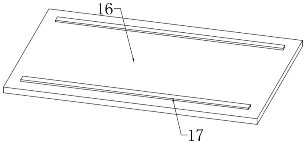
[0025] In order to further explain the above-mentioned reciprocating steel plate cutting device based on the principle of slider crank, the application provides another embodiment. The reciprocating steel plate cutting device based on the principle of slider crank in this embodiment has the following technical features: A workbench 16 is arranged above the supporting plate 1, and the top of the two sides of the workbench 16 is fixedly connected to the piston rod 15, and the upper part of the piston rod 15 is sealed and slidably connected to the cylinder 14, and the cylinder 14 is fixed on the columns 2 on both sides, and the front and rear sides of the workbench 16 The pads 17 are respectively fixedly connected, and the cylinder 14 drives the piston rod 15 to stretch and then drives the workbench 16 to move up and down to realize height adjustment, which is convenient for cutting steel plates of different thicknesses, and the pads 17 are used to pad the steel plates to prevent t...


PUM


Abstract

The invention discloses a reciprocating steel plate cutting device based on the principle of a crank slider, and relates to a device capable of automatically walking and reciprocatingly cutting steel plates. The device drives a stepped shaft and a worm to rotate through a sleeve, and the rotating worm drives a worm wheel to rotate to drive The cutting wheel rotates to realize the cutting function. At the same time, the rotating sleeve drives the rotating shaft and the turntable to rotate through the first bevel gear and the second bevel gear. Cutting function, and, through the cooperation of the cylinder and the piston rod, the height of the workbench can be adjusted to realize the cutting of steel plates of different thicknesses. The present invention effectively solves the problems of complex structure of the existing steel plate cutting machine, the cutting function needs to be realized through synergy of multiple power mechanisms at the same time, and the problems of high manufacturing and use costs.

Description

technical field [0001] The invention relates to a mechanical processing and cutting device, in particular to a reciprocating steel plate cutting device based on the principle of a crank slider. Background technique [0002] The steel plate is a flat steel that is poured with molten steel and pressed after cooling. The steel plate is widely used, such as bridge steel plate, boiler steel plate, automobile manufacturing steel plate, pressure vessel steel plate and multi-layer high pressure vessel steel plate, etc. In addition, in spring steel, stainless steel , tool steel, heat-resistant steel, bearing steel, silicon steel and industrial pure iron sheet occupy an important position. [0003] After the steel plate is cast out of the furnace, the area is often large, which is not conducive to handling and transportation. In the actual production and application process, it is usually cut to make it into a small plate that is more convenient for transportation. The existing steel ...

Claims


Application Information

Patent Timeline
Patent Type & Authority Patents(China)
IPC IPC(8): B23D47/00B23D47/02B23Q5/28B23Q1/25
Inventor 戎珊珊
Owner 广西桂盾人防工程有限公司
Learn More