
WIFI energy collection system

A technology of energy collection and capacitance, which is applied in transmission systems, impedance networks, electrical components, etc., can solve problems such as energy loss, low energy collection efficiency, and DC signal fluctuations, and achieve high safety and stability

Active Publication Date: 2019-06-11
NINGBO UNIV
View PDF5 Cites 3 Cited by
  • Summary
  • Abstract
  • Description
  • Claims
  • Application Information

AI Technical Summary

Problems solved by technology

[0005] However, the existing WIFI energy harvesting system has the following problems: 1. The impedance of the antenna module is not equal to the total load impedance of other modules in the WIFI energy harvesting system, so when the antenna module collects WIFI signals, the WIFI signal will inevitably reflect a part Energy, resulting in energy loss, which leads to low energy collection efficiency; Second, the DC signal obtained through the DC-DC module inevitably fluctuates, which leads to the instability of the output voltage of the energy storage module

Method used


Image

  • WIFI energy collection system
  • WIFI energy collection system
  • WIFI energy collection system

Examples


Embodiment 1

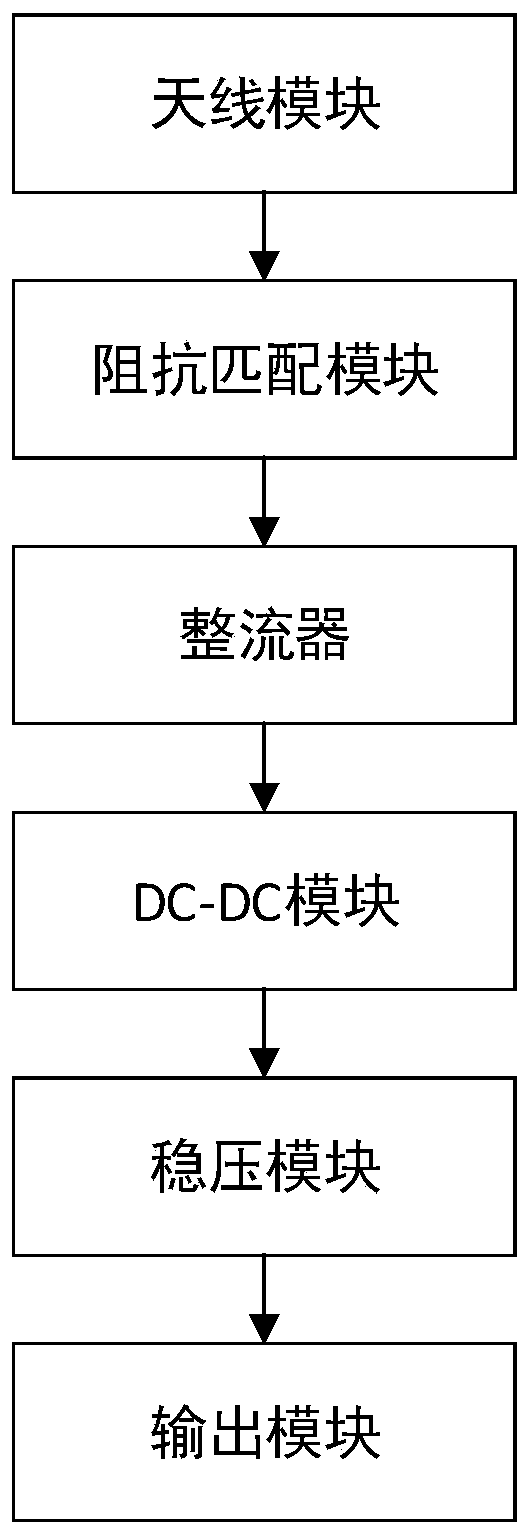
[0021] Embodiment one: if figure 1 As shown, a WIFI energy harvesting system includes an antenna module, a rectifier, and a DC-DC module. The WIFI energy harvesting system also includes an impedance matching module, a voltage stabilizing module for stabilizing the DC signal output by the DC-DC module, and An output module that can suppress instantaneous high voltage and is used to output DC voltage, and the impedance matching module is used to match the antenna module with the rectifier, the DC-DC module, the voltage stabilization module and the The total load impedance of the output module described above, the output end of the antenna module is connected to the input end of the impedance matching module, the output end of the impedance matching module is connected to the input end of the rectifier, and the output end of the rectifier is connected to the input end of the DC-DC module. The output end of the DC-DC module is connected to the input end of the voltage stabilizing ...

Embodiment 2

[0022] Embodiment two: this embodiment is generally the same as embodiment one, and the difference is as follows:

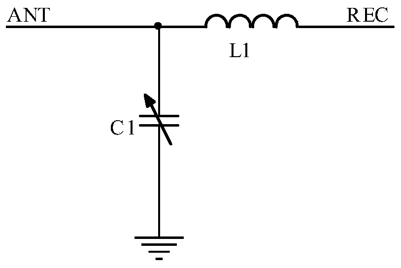
[0023] Such as figure 2 As shown, in this embodiment, the impedance matching module includes a first inductor L1 and a first capacitor C1, the first capacitor C1 is a variable capacitor, one end of the first inductor L1 is connected to one end of the first capacitor C1 and its connection end is The input end of the impedance matching circuit, the other end of the first capacitor C1 is grounded, and the other end of the first inductor L1 is the output end of the impedance matching circuit.

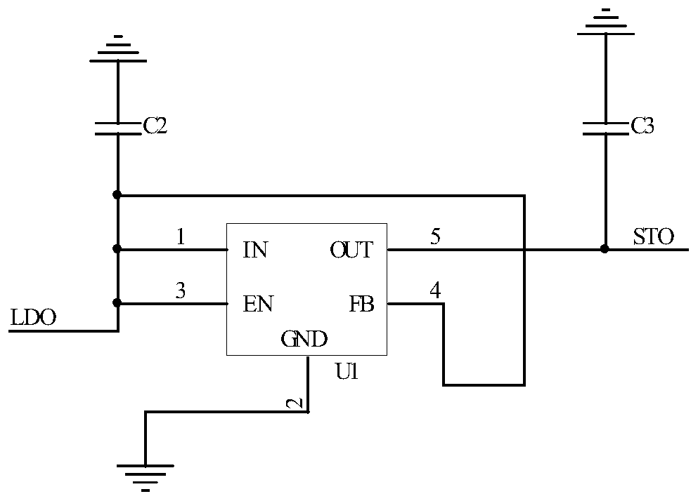
[0024] Such as image 3 As shown, in this embodiment, the voltage stabilizing module includes a voltage stabilizing chip U1 whose model is TPS780330220DDCR, a second capacitor C2 and a third capacitor C3, the first pin, the third pin, the fourth pin and the second pin of the voltage stabilizing chip U1 One end of capacitor C2 is connected and its connection end is the input...


PUM


Abstract

The invention discloses a WIFI energy collection system, including an antenna module, a rectifier and a DC-DC module. The WIFI energy collection system also comprises an impedance matching module anda voltage stabilizing module used for stabilizing the voltage of the direct current signal outputted by the DC-DC module; and the impedance matching module is used for matching the total load impedance of the antenna module, the rectifier, the DC-DC module, the voltage stabilizing module and the output module. The output end of the antenna module is connected with the input end of the impedance matching module; the output end of the impedance matching module is connected with the input end of the rectifier, the output end of the rectifier is connected with the input end of the DC-DC module, the output end of the DC-DC module is connected with the input end of the voltage stabilizing module, and the output end of the voltage stabilizing module is connected with the input / output end of the output module. The WIFI energy collection system has the advantages of high energy collection efficiency and high output voltage safety and stability.

Description

technical field [0001] The invention relates to an energy collection system, in particular to a WIFI energy collection system. Background technique [0002] With the rapid development of industrial technology, various electronic devices have entered people's lives. These electronic devices all need to provide working energy (electric energy) from outside to work normally. At present, there are two main ways to provide working energy for these electronic devices: external mains power and batteries. Working energy provided by external mains needs to consume existing resources, and battery working energy produces waste batteries, which pollutes the environment. [0003] With the development of WIFI technology, WIFI networks are everywhere in people's life and work. People began to study extracting energy from WIFI signals as functional energy for electronic devices. Extracting energy from WIFI signals neither consumes existing resources nor produces environmental pollution....

Claims


Application Information

Patent Timeline
Patent Type & Authority Applications(China)
IPC IPC(8): H03H7/38H04B1/40
Inventor 张涛谢志军陈海明江先亮
Owner NINGBO UNIV
Learn More