Parallel seam welding repairing and plugging device
A parallel seam welding and rework technology, which is applied in the manufacture of electrical components, semiconductor/solid-state devices, circuits, etc., can solve problems such as flatness and other quality control, burrs on the surface of the tube seat, and small thickness of the welding cover, etc. Maintenance cost and maintenance work intensity, accelerated curing speed, and the effect of avoiding glue clogging
- Summary
- Abstract
- Description
- Claims
- Application Information
AI Technical Summary
Problems solved by technology
Method used
Image

Examples
Embodiment 1
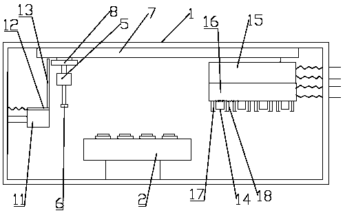
[0025] Such as Figure 1 to Figure 2 As shown, a parallel seam welding rework plugging device includes a box body 1, and a workbench 2 is movable inside the box body. The workbench 2 can rotate and move up and down. Electric telescoping rod is realized. Workbench 2 is provided with a number of clamping seats arranged regularly. The clamping seats are used for clamping reworked products. The horizontal clamping seats form a horizontal clamping seat group, and the vertical clamping seats form a vertical clamping seat group. The number of seat groups is equal.
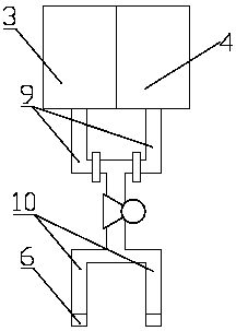
[0026] A liquid application mechanism is provided in the cabinet 1 to move left and right through a shift mechanism, which is used for applying glue to the reworked product and cleaning the surface of the reworked product after the glue coating is completed. Specifically, the liquid application mechanism includes a mounting plate 8 and several liquid application parts arranged thereon. The liquid application parts inclu...
Embodiment 2
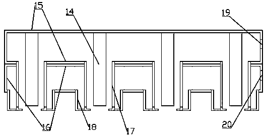
[0033] Such as figure 1 and image 3 As shown, in order to speed up the curing speed of the anaerobic adhesive, in the present embodiment, an auxiliary curing mechanism is movable through the displacement mechanism in the box body 1. The auxiliary curing mechanism includes an air inlet shell 15 and an air outlet shell 16 arranged up and down. The box body 1 is provided with an air inlet and an air outlet, and the air inlet shell 15 and the air outlet shell 16 are respectively provided with an air inlet hole 19 and an air outlet hole 20, and the air inlet hole 19 and the air outlet hole 20 are respectively connected to the air inlet by a telescopic hose And the air outlet, the inner wall of the top of the air inlet shell 15 is provided with several stoppers 14 downwards, the number and position of the stoppers 14 are matched with the clamping seat on the workbench 2, the stoppers 14 protrude through the air outlet shell 16, and the stoppers The outside of the block 14 is provi...
PUM
 Abstract
Description
Claims
Application Information
PatSnap Eureka turns technology decisions into work you can execute. Powered by our Innovation Knowledge Graph, it runs expert workflows across engineering, life sciences, materials and intellectual property. Get your review-ready output in minutes.


