
Fundus camera with coaxial lighting source and fixation light source

A technology of lighting source and light source, which is applied in ophthalmoscope, equipment for testing eyes, medical science, etc. It can solve problems such as inability to adjust focus, stray light, and inability to adjust focus of photosensitive elements

Inactive Publication Date: 2019-06-18
BEIJING CHIOY MEDICAL TECH CO LTD
View PDF3 Cites 7 Cited by
  • Summary
  • Abstract
  • Description
  • Claims
  • Application Information

AI Technical Summary

Problems solved by technology

At present, the illumination light path of the hand-held fundus camera is separated from the fixation light path; in addition, the fixation light path of some fundus cameras is installed in the fundus mirror of the fundus camera, which cannot be adjusted according to the diopter of the eyeball of the testee. Focusing; the fixation light path of some fundus cameras passes through the entire imaging light path, which will introduce stray light
[0006] In the existing fundus camera, the light source of the fixation light is introduced through the imaging optical path, passing through the entire imaging optical path from the conjugate position of the photosensitive element, which will introduce stray light, and a small dot will appear in the middle of the collected image. The dot is the fixation light; in some existing fundus cameras, the light source of the fixation light is imported through an external optical path, and the light source of the fixation light is installed in the ophthalmoscope, which is not in a conjugate relationship with the photosensitive element, and cannot be adjusted together with the photosensitive element.

Method used


Image

  • Fundus camera with coaxial lighting source and fixation light source
  • Fundus camera with coaxial lighting source and fixation light source
  • Fundus camera with coaxial lighting source and fixation light source

Examples


Embodiment Construction

[0034] The following will clearly and completely describe the technical solutions in the embodiments of the present invention with reference to the accompanying drawings in the embodiments of the present invention. Obviously, the described embodiments are only some, not all, embodiments of the present invention. Based on the embodiments of the present invention, all other embodiments obtained by persons of ordinary skill in the art without making creative efforts belong to the protection scope of the present invention.

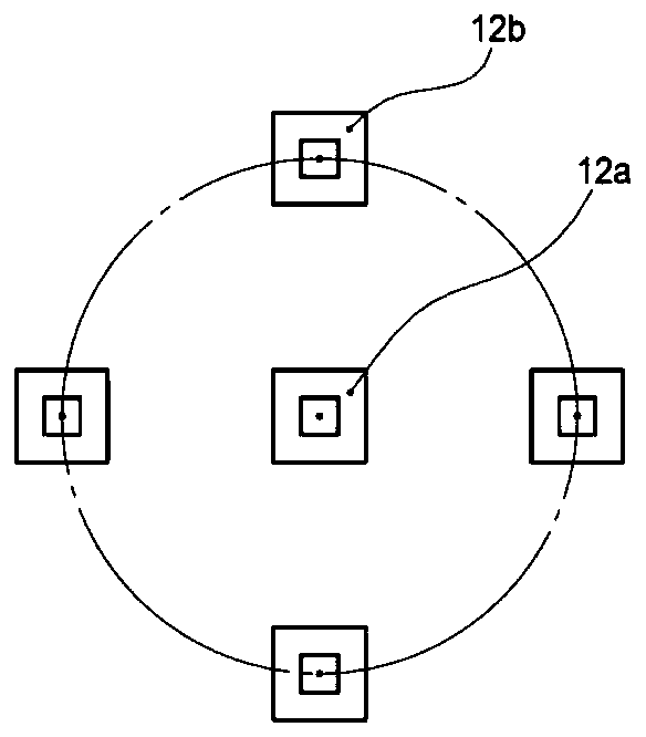
[0035] see Figure 1-10, the present invention provides a technical solution: a fundus camera with the coaxial illumination light source and the fixation light source, the body optical assembly 1 includes a photosensitive element 11, a fixation lamp assembly 12 (the fixation lamp assembly 12 includes a central fixation Lamp light emitting unit 12a, comprising 0 several edge fixation lamp light emitting units 12b); Ophthalmoscope optical assembly 2 comprises fi...


PUM


Abstract

The invention discloses a fundus camera with a coaxial lighting source and fixation light source. The fundus camera comprises a machine body optical assembly, an ophthalmoscope optical assembly and eyes, wherein the machine body optical assembly comprises a photosensitive element and a fixation lamp assembly, the photosensitive element is used for acquiring an image of the fundus, the fixation lamp assembly is used for guiding a tested person for fundus imaging, the fixation lamp assembly comprises a central fixation lamp light emitting unit and an edge fixation lamp light emitting unit, the ophthalmoscope optical assembly comprises a first lens group, a second lens group, a third lens group, an incident polarizer, a beam splitter, an emergent polarizer and a lighting source assembly. Thefundus camera with the coaxial lighting source and fixation light source has the advantages that it is avoided that stray light generated by the lighting source enters a subsequent imaging optical path to the photosensitive element, it is also avoided that stray light generated by the fixation light source enters the subsequent imaging optical path to the photosensitive element, and only diffuse reflection light depolarized in a fundus area can pass through the emergent polarizer.

Description

technical field [0001] The invention relates to the field of fundus cameras, in particular to a fundus camera in which an illumination light source and a fixation light source are coaxial. Background technique [0002] Fundus photography is a widely used diagnostic item in ophthalmology. The blood vessels of the fundus are the only blood vessels that can be directly observed through the body surface. Using a fundus camera, doctors can check whether there are lesions in the optic nerve, retina, choroid and refractive medium of the fundus. At the same time, with the assistance of the fundus camera, other systemic diseases can be diagnosed and judged, such as cerebral infarction, cerebral hemorrhage, cerebral arteriosclerosis, brain tumor, diabetes, kidney disease, high blood pressure, etc. [0003] Traditional desktop fundus cameras include complex lighting systems and observation systems, which are huge in size and complex in system structure. Some instruments need to install...

Claims


Application Information

Patent Timeline
IPC IPC(8): A61B3/12A61B3/15
Inventor 陈凯徐亮禹胡鹏
Owner BEIJING CHIOY MEDICAL TECH CO LTD
Learn More