
Three-rotor-wing unmanned aerial vehicle capable of vertically taking off, landing and tilting

A vertical take-off and landing, tri-rotor technology, applied in the field of unmanned aerial vehicles, can solve the problems of reduced use efficiency of unmanned aerial vehicles, short battery life, short control distance, etc., and achieve compact structure, long battery life, and low power consumption. Effect

Pending Publication Date: 2019-06-18
GUANGZHOU TIAN HAI XIANG AVIATION TECH
View PDF0 Cites 2 Cited by
  • Summary
  • Abstract
  • Description
  • Claims
  • Application Information

AI Technical Summary

Problems solved by technology

[0002] UAV is a kind of unmanned aircraft mainly controlled by radio remote control or by itself. UAV is widely used in aerial photography, rescue, inspection, monitoring, surveying and mapping, investigation, film and television shooting, news report, express transportation and other fields. Most of the existing multi-rotor drones have weak wind resistance, slow flight speed, and short battery life. When encountering bad weather, the efficiency of drones is greatly reduced, while fixed-wing unmanned vehicles mainly use propellers or The thrust generated by the turbine engine makes the UAV move forward. The main lift comes from the relative movement between the wing and the air, which is relatively economical. However, fixed-wing UAVs have high requirements for take-off and landing sites and flight operations. The lift generated by multiple rotors balances the gravity of the aircraft and allows the drone to fly. However, the existing multi-rotor drones have short control distances and short battery life.

Method used


Image

  • Three-rotor-wing unmanned aerial vehicle capable of vertically taking off, landing and tilting
  • Three-rotor-wing unmanned aerial vehicle capable of vertically taking off, landing and tilting
  • Three-rotor-wing unmanned aerial vehicle capable of vertically taking off, landing and tilting

Examples


Embodiment Construction

[0023] The following will clearly and completely describe the technical solutions in the embodiments of the present invention with reference to the accompanying drawings in the embodiments of the present invention. Obviously, the described embodiments are only some, not all, embodiments of the present invention. Based on the embodiments of the present invention, all other embodiments obtained by persons of ordinary skill in the art without making creative efforts belong to the protection scope of the present invention.

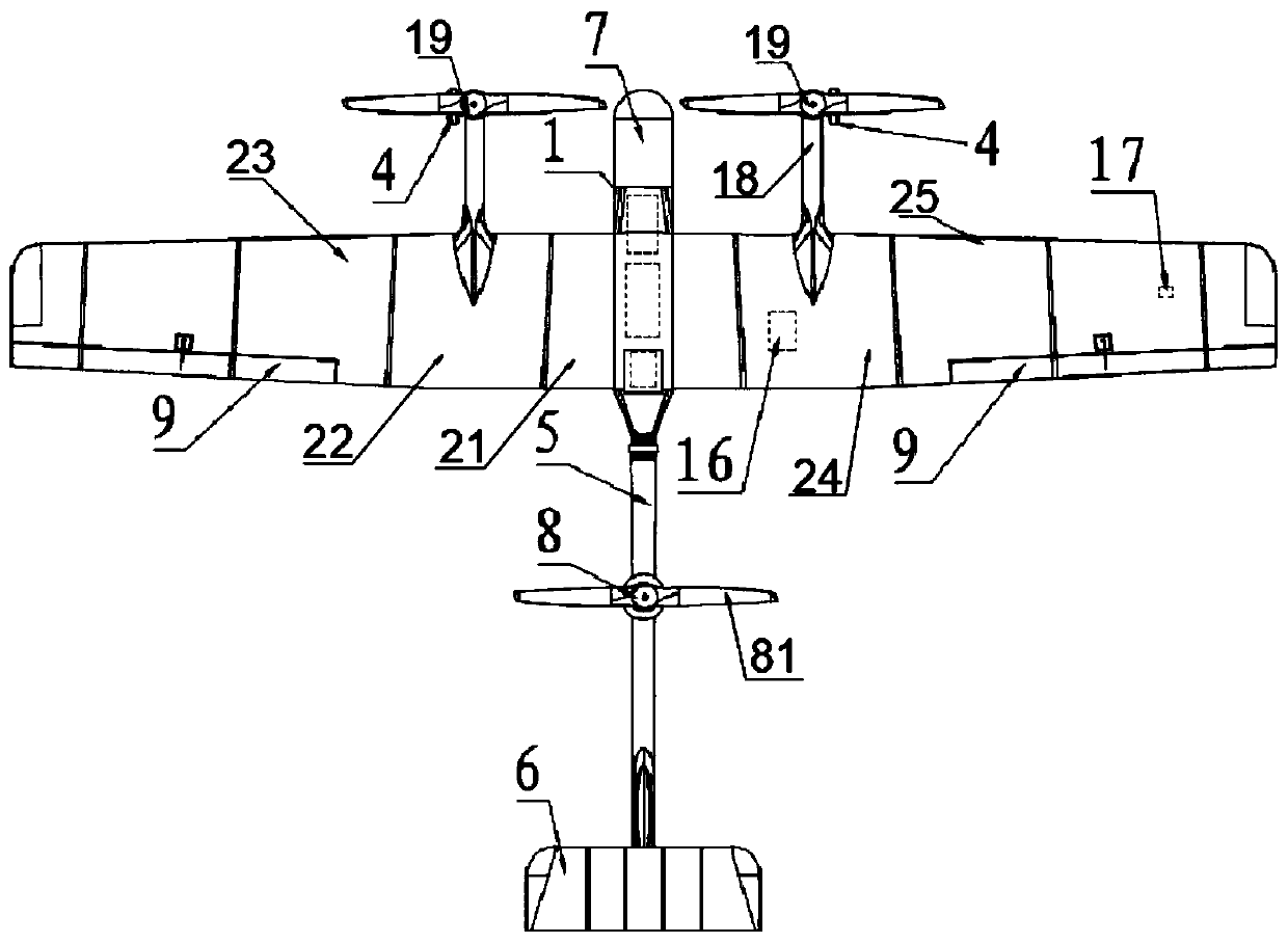
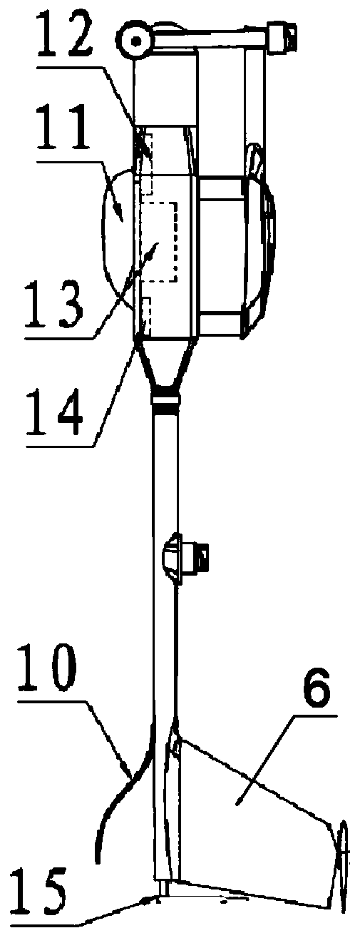
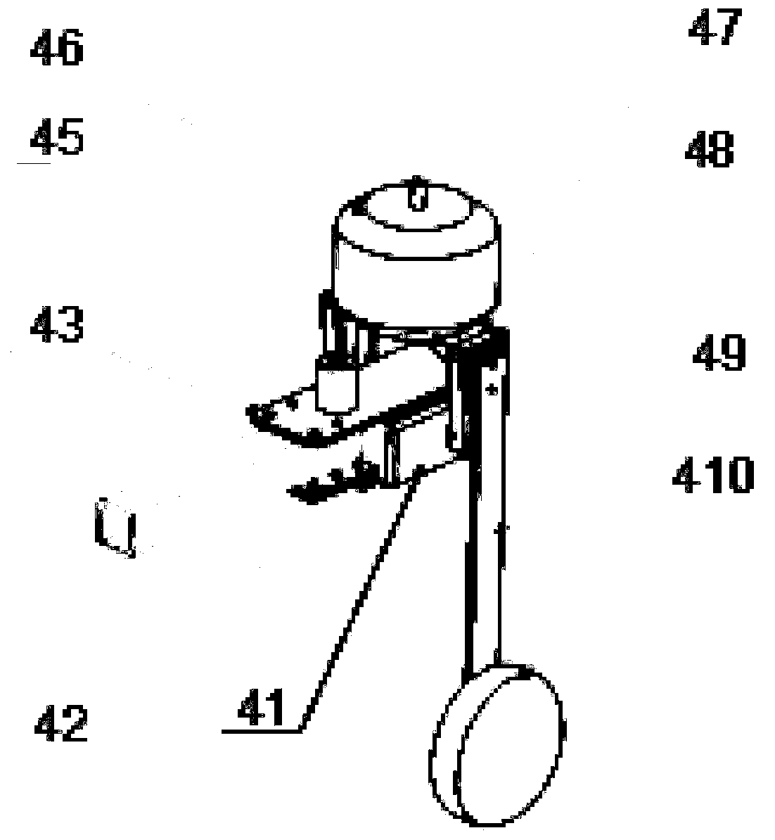
[0024] like Figure 1-Figure 4 Shown is a schematic structural diagram of an embodiment of a vertical take-off and landing tilting three-rotor UAV provided by the present invention: including a fuselage 1, the fuselage 1 is made of a composite material made of Kevlar and carbon fiber, and the fuselage 1 An image data transmission system 12, a power supply battery 13, and a flight control system 14 are installed inside. The power supply battery 13 is a magnesiu...


PUM


Abstract

The invention discloses a three-rotor-wing unmanned aerial vehicle capable of vertically taking off, landing and tilting. The three-rotor-wing unmanned aerial vehicle comprises a vehicle body. Wings,including a middle wing, a left wing and a right wing, are arranged on two sides of the vehicle body. The left wing and the right wing are connected to two sides of the middle wing respectively. Overhung rods are arranged on the left wing and the right wing respectively and are parallel and symmetrical to each other. A tilting mechanism is mounted on each overhung rod, and a rotor wing is connected to each tilting mechanism. A reconnaissance system is mounted at the front end of the vehicle body. A tail rod is mounted at the rear end of the vehicle body, a power device is mounted on the tail rod, and a horizontal tail wing is mounted at the end of the tail rod. The three-rotor-wing unmanned aerial vehicle has the advantages of convenience in assembly and disassembly, long flight duration,compact structure and portability.

Description

technical field [0001] The invention relates to the technical field of unmanned aerial vehicles, in particular to a vertical take-off and landing tilting three-rotor unmanned aerial vehicle. Background technique [0002] UAV is a kind of unmanned aircraft mainly controlled by radio remote control or by itself. UAV is widely used in aerial photography, rescue, inspection, monitoring, surveying and mapping, investigation, film and television shooting, news report, express transportation and other fields. Most of the existing multi-rotor drones have weak wind resistance, slow flight speed, and short battery life. When encountering bad weather, the efficiency of drones is greatly reduced, while fixed-wing unmanned vehicles mainly use propellers or The thrust generated by the turbine engine makes the UAV move forward. The main lift comes from the relative movement between the wing and the air, which is relatively economical. However, fixed-wing UAVs have high requirements for tak...

Claims


Application Information

Patent Timeline
IPC IPC(8): B64C27/08B64C27/32B64C27/52B64C25/34B64D45/00B64C29/00
Inventor 裴洪涛许俊志吴宗曼李裕壮吴开兴庞海杰高爽徐文华
Owner GUANGZHOU TIAN HAI XIANG AVIATION TECH
Learn More