Self-adjusting type crank drum type brake

A drum brake, self-adjusting technology, applied to drum brakes, brake types, brake parts, etc., can solve the problems of low work efficiency, insufficient space for brake installation, affecting vehicle braking performance, etc., and achieve a compact structure. Effect

Pending Publication Date: 2019-06-18
靖江市恒大汽车部件制造有限公司
View PDF6 Cites 3 Cited by
  • Summary
  • Abstract
  • Description
  • Claims
  • Application Information

AI Technical Summary

Problems solved by technology

After the camshaft is equipped with an automatic adjustment arm, the clearance adjustment mechanism is externally placed on the shaft end of the brake camshaft to realize synchronous adjustment of the braking clearance of the collar and the follower shoe, but there is a risk of over-adjustment of the brake clearance; With the continuous adjustment and compensation of the gap, the "S" shape of the camshaft is constantly opened, and when it is close to the limit position, there is a situation that the camshaft cannot return due to overturning
[0003] In the prior art, the brake shoe of the drum brake generally adopts a structure that rotates around the pin shaft. During the brake wear process, the frictional contact area between the brake shoe that rotates around the fixed shaft and the hub cannot be guaranteed to be uniform, which affects the The braking performance of the vehicle; moreover, the installation position of the return spring used for the brake shoe reset in the prior art also limits the space of the brake when the axle housing is assembled, so that the space for the brake to install the bridge is insufficient, and the operation is troublesome and laborious. low efficiency

Method used


Image

  • Self-adjusting type crank drum type brake
  • Self-adjusting type crank drum type brake
  • Self-adjusting type crank drum type brake

Examples


Embodiment Construction

[0035] The specific implementation manner of the present invention will be described below in conjunction with the accompanying drawings.

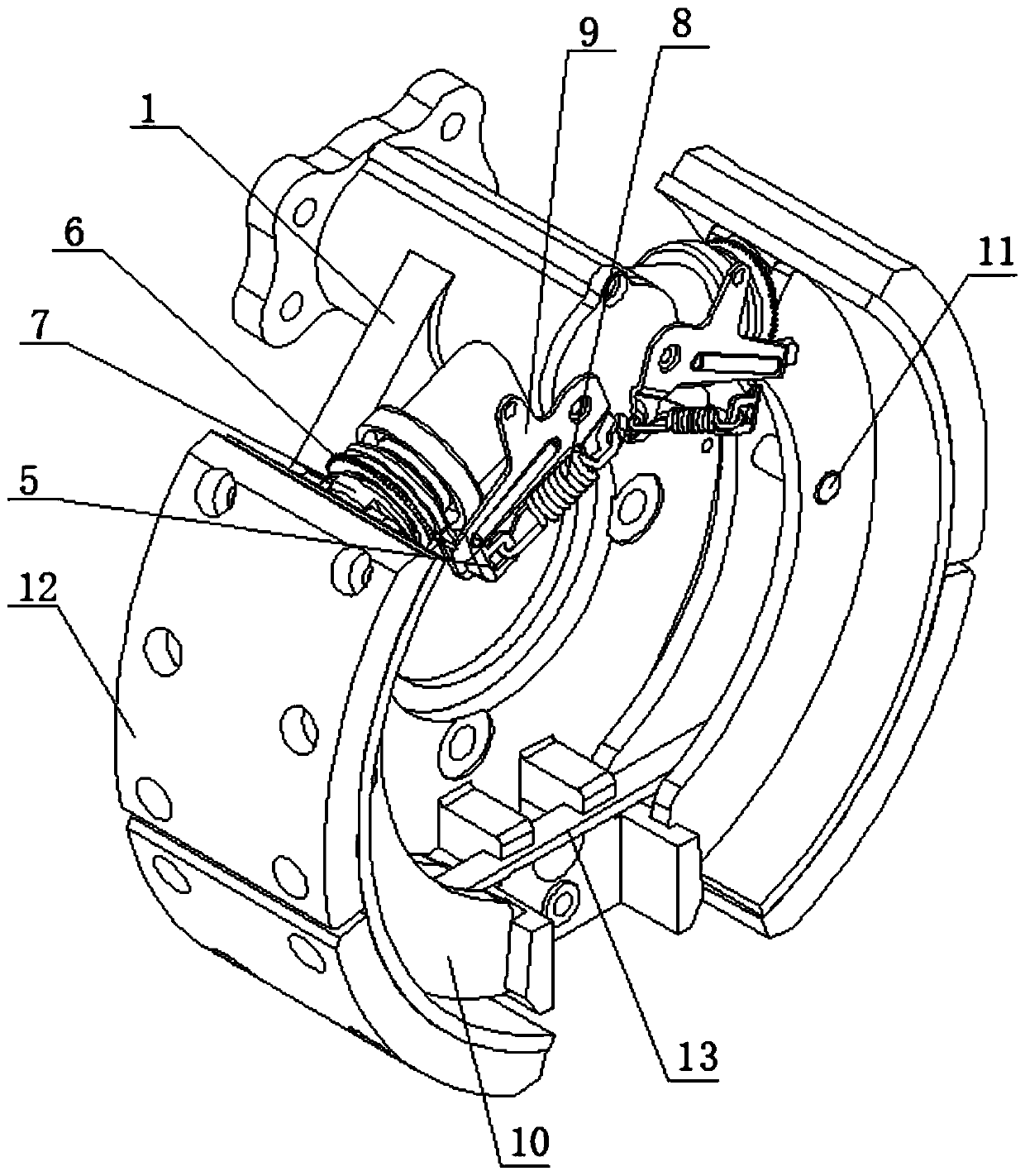
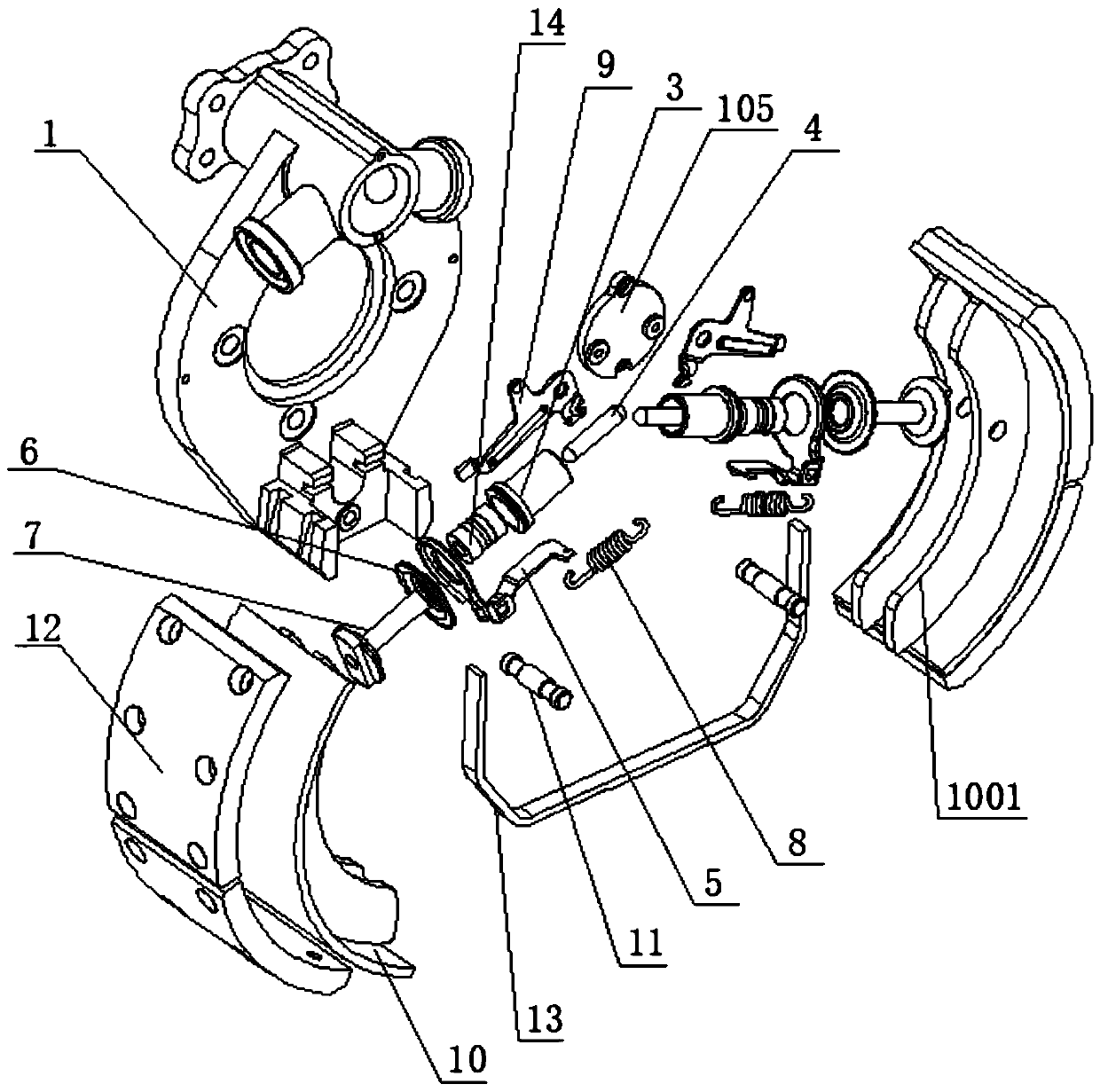
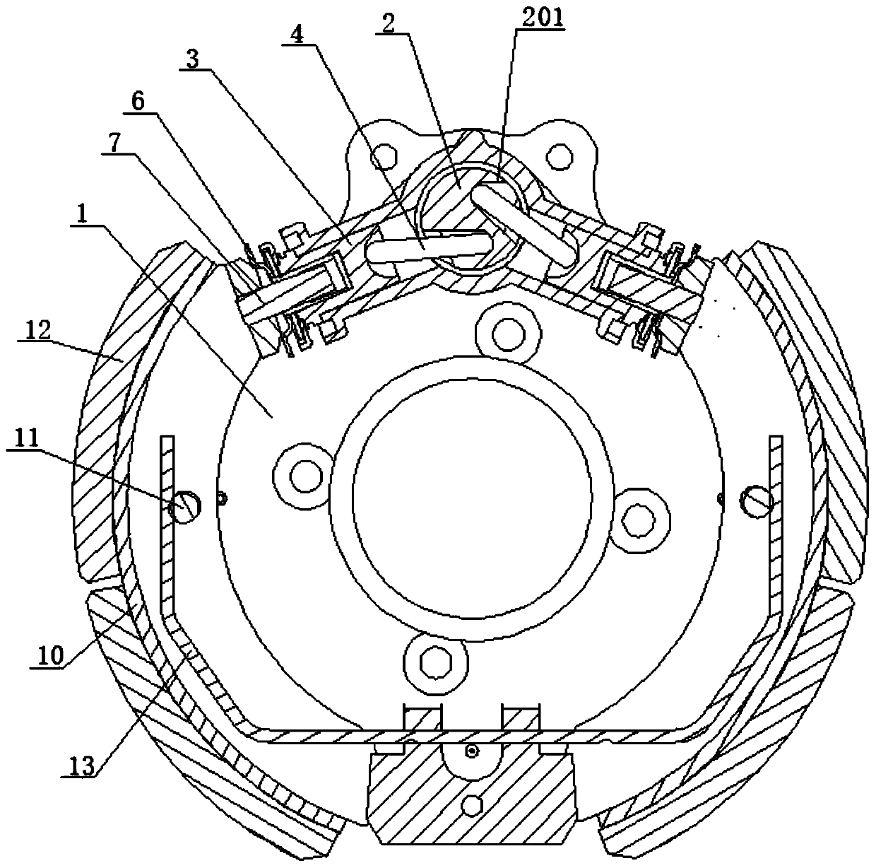
[0036] Such as figure 1 , figure 2 , image 3 , Figure 4 and Figure 5 As shown, the self-adjusting crank drum brake of this embodiment includes a brake base plate 1, and arc-shaped brake shoes 10 are arranged symmetrically on both sides of the front end of the brake base plate 1. The top surface of the brake base plate 1 is provided with a crank cylinder block 101, such as Figure 6As shown, a crank cam 2 is installed inside the crank cylinder 101, and there are two bent side cylinders 103 extending outward from the crank cylinder 101, and a piston 3 is installed inside each side cylinder 103, and the end of the piston 3 is connected to the The crank cam 2 is connected through the connecting rod 4; the end of the single side cylinder 103 is equipped with an adjusting screw 7, the adjusting screw 7 is covered with a ratchet 6 and a ...


PUM


Abstract

The invention relates to a self-adjusting type crank drum type brake which comprises a braking bottom plate. Two braking shoes in floating connection with the braking bottom plate are symmetrically arranged on the side face of the braking bottom plate. A crank cylinder body is arranged at the upper end of the braking bottom plate. A crank cam is installed in the crank cylinder body. Two side cylinder bodies extend from the exterior of the crank cylinder body. A piston is installed in each side cylinder body. An adjusting screw rod, a ratchet wheel and a plate are installed on the end portion of each side cylinder body. One end of each adjusting screw rod extends into the corresponding piston, and the other end of each adjusting screw rod directly faces the braking shoes. An adjusting and pulling plate is installed at the front end of the crank cylinder body, one end of the adjusting and pulling plate is clamped with the plates, and the other end of the adjusting and pulling plate makestooth contact with the ratchet wheels. The two braking shoes are mutually connected through a return plate spring. A pulling spring is further installed. According to the brake, an automatic gap adjusting device is arranged in the brake, the two braking shoes are adjusted independently, and the braking stability is improved. After braking, resetting is achieved through the return plate spring, due to the design of the return plate spring, enough space is reserved for assembling the brake, and the assembling efficiency is improved.

Description

technical field [0001] The invention relates to the technical field of vehicle brakes, in particular to a self-adjusting crank drum brake. Background technique [0002] Domestic pneumatic drum brakes mainly adopt "S" type camshaft structure. GB7258-2017 requires that all brakes must be equipped with an automatic adjustment device for brake clearance starting from January 2018. The existing "S" type camshaft structure matches the automatic adjustment. The arm can meet this requirement of the regulations and realize the automatic adjustment of the clearance. After the camshaft is equipped with an automatic adjustment arm, the clearance adjustment mechanism is externally placed on the shaft end of the brake camshaft to realize synchronous adjustment of the braking clearance of the collar and the follower shoe, but there is a risk of over-adjustment of the brake clearance; With the continuous adjustment and compensation of the gap, the "S" shape of the camshaft is continuously ...

Claims


Application Information

Patent Timeline
Patent Type & Authority Applications(China)
IPC IPC(8): F16D51/20F16D65/09F16D65/18F16D65/56F16D121/14F16D121/04
Inventor 徐宇吴玉初吴进乔冠朋
Owner 靖江市恒大汽车部件制造有限公司
Why Eureka
Try Eureka